
Instructions


RIGOL
8 MSO7000/DS7000 Quick Guide
English
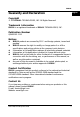
Figure 3 User Interface
Table 3 User Interface Icons
No.
Description
No.
Description
1
Analog Channel Label and Waveform
13
Operation Menu
2
Operating Status
14
Notification Area
3
Horizontal Time Base
15
Arbitrary Waveform Generator 2
Waveform Label
4
Sample Rate and Memory Depth
16
Arbitrary Waveform Generator 1
Waveform Label
5
Auto Measurement Label
17
Digital Channel Status Area
6
Waveform Memory
18
CH4 Status Label
7
Trigger Position
19
Message Box
8
RUN/STOP Label
20
CH3 Status Label
9
Horizontal Position
21
CH2 Status Label
10
Trigger Type
22
CH1 Status Label
11
Trigger Source
23
Digital Channel Label and Waveform
12
Trigger Level/Threshold Level
24
Function Navigation
24 23 22 21 20 19 18 17 16 15 14 13
1 2 3 4 5 6 7 8 9 10 11 12