
User Guide


Chapter 18 Specifications RIGOL
MSO1000Z/DS1000Z User’s Guide 18-5
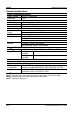
Data Bits
5 bit, 6 bit, 7 bit, 8 bit
I2C Trigger (Option)
Trigger
Condition
Start, Restart, Stop, Missing ACK, Address, Data, A&D
Address Bits
7 bits, 8 bits, 10 bits
Address Range
0x0 to 0x7F, 0x0 to 0xFF, 0x0 to 1023
Byte Length
1 to 5
SPI Trigger (Option)
Trigger
Condition
Timeout, CS
Timeout Value
16 ns to 10 s
Data Bits
4 bit to 32 bit
Data Line
Setting
H, L, X
Measure
Cursor
Manual Mode
Voltage Deviation between Cursors (△V)
Time Deviation between Cursors (
△
T)
Reciprocal of
△
T (Hz) (1/
△
T)
Track Mode
Voltage and Time Values of the Waveform
Point
Auto Mode
Allow to display cursors during auto
measurement
Auto
Measurement
Analog channel:
Period, Frequency, Rise Time, Fall Time, Positive Pulse Width,
Negative Pulse Width, Positive Duty Cycle, Negative Duty Cycle,
tVmax, tVmin, Positive Rate, Negative Rate, Delay 12
, Delay
12
, Phase 12 , Phase 12 , Maximum, Minimum,
Peak-Peak Value, Top Value, Bottom Value, Amplitude, Upper
Value, Middle Value, Lower Value, Average, Mean Square Root,
Overshoot, Pre-shoot, Area, Period Area, Variance
Digital channel:
Frequency, Period, Positive Pulse Width, Negative Pulse Width,
Positive Duty Cycle, Negative Duty Cycle, Delay 12
, Delay
12 , Phase 12 , Phase 12
Number of
Measurements
Display 5 measurements at the same time.
Measurement
Range
Screen or cursor
Measurement
Statistic
Average, Max, Min, Standard Deviation, Number of
Measurements
Frequency
Counter
Hardware 6 bit frequency counter
(channels are selectable)