
User Guide


RIGOL Chapter 6 MATH and Measurement
6-30 MSO1000Z/DS1000Z User’s Guide
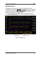
Figure (c) Figure (d) Figure (e)
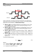
AX: the X value at cursor A. X value takes the trigger position as reference. Its
unit is “s” or “Hz” (when measuring FFT waveform).
AY: the Y value at cursor A. Y value takes the channel GND of CH1 as reference.
Its unit is the same as that of the current signal source.
BX: the X value at cursor B. X value takes the trigger position as reference. Its
unit is “s” or “Hz” (when measuring FFT waveform).
BY: the Y value at cursor B. Y value takes the channel GND of CH1 as reference.
Its unit is the same as that of the current signal source.
BX-AX: the horizontal difference between cursors A and B.
BY-AY: the vertical difference between cursors A and B.
|dX|: when the horizontal unit selects “s”, |dx| represents the time difference
between cursors A and B; when the horizontal unit selects “Hz”, |dx| represents
the frequency difference between cursors A and B;
1/|dX|: the frequency difference between cursors A and B.
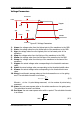
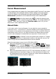
When the measurement source is set to LA, the measurement results will be
displayed at the upper-left corner of the screen in the following form.
AX: the X value at cursor A. X value takes the trigger position as reference.
D15-D0: display the logic level values at cursor A (D15-D0 from left to right) in
hexadecimal forms. If the digital channel is currently turned off, it will be
denoted by “*”.
BX: the X value at cursor B. X value takes the trigger position as reference.
D15-D0: display the logic level values at cursor B (D15-D0 from left to right) in
hexadecimal forms. If the digital channel is currently turned off, it will be
denoted by “*”.
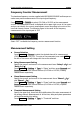
If needed, please refer to the following steps to modify the parameters of manual
cursor measurement.
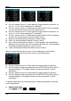
1. Select Cursor Type
Press Select to select “ ” or “ ”.