
User`s guide

RIGOL
© 2008 RIGOL Technologies, Inc.
User’s Guide for DS1000E, DS1000D Series
2-59
Trigger, such as the output of Power supply.
NOTE: When horizontal control is set under 50 ms/div, Auto mode allows the
oscilloscope not to capture trigger signal.
Normal:
The Normal mode allows the oscilloscope to acquire a waveform only when it is
triggered. If no trigger occurs, the oscilloscope keeps waiting, and the previous
waveform, if any, will remain on the display.
Single:
In Single mode, after pressing the RUN/STOP key, the oscilloscope waits for
trigger. While the trigger occurs, the oscilloscope acquires one waveform then
stop.
3. Coupling:
Trigger coupling determines which signal component passing to the trigger circuit.
Coupling types include AC, DC, LF Reject and HF Reject.
AC: AC coupling blocks DC components and attenuates the signal below
10Hz.
DC: DC coupling passes both AC and DC components.
LF Reject: LF Reject coupling blocks DC component, and attenuates all
signal with a frequency lower than 8 kHz.
HF Reject: HF Reject coupling attenuates all signals with a frequency
higher than 150 kHz.
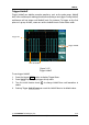
4. Pre-trigger/delayed trigger:
The data collected before and after trigger.
The trigger position is typically set at the horizontal center of the screen. In the
full-screen display the 6div data of pre-trigger and delayed trigger can be
surveyed. More data (14div) of pre-trigger and 1s delayed trigger can be
surveyed by adjusting the horizontal knob.