
User`s guide

RIGOL
© 2008 RIGOL Technologies, Inc.
User’s Guide for DS1000E, DS1000D Series
2-32
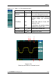
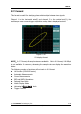
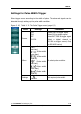
Marks Indicator
① The current waveform window’s position in the memory.
② The trigger position in the memory.
③ The trigger position in the current waveform windows.
④ The horizontal time base (main time base).
⑤ The trigger’s horizontal offset according to the center of the window.
Key Points
Y-T: The conventional oscilloscope display format. It shows the voltage of a
waveform record (on the vertical axis) as it varies over time (on the
horizontal axis).
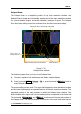
X-Y: XY format displays channel 1 in the horizontal axis and channel 2 in the
vertical axis.
Roll Mode: In this mode, the waveform display rolls from right to left. No trigger
or horizontal offset control of waveforms is available during Roll Mode, and
it’s only available when set to 500 ms/div or slower.
Slow Scan Mode: This mode is available when the horizontal time base is set to
50ms/div or slower. In this mode, the oscilloscope acquires sufficient data
for the left part to the trigger point, then wait for trigger, when trigger
occurs, it continues to draw the rest part from the trigger point to the end of
the right side. When choosing this mode to view low frequency signals, it is
recommended that the channel coupling be set as DC.
Time/Div: Horizontal scale. If the waveform acquisition is stopped (using the
RUN/STOP button), the Time/Div control expands or compresses the
waveform.