RIGOL Programming Guide DP800 Series Programmable Linear DC Power Supply Mar. 2013 RIGOL Technologies, Inc.
RIGOL Guaranty and Declaration Copyright © 2013 RIGOL Technologies, Inc. All Rights Reserved. Trademark Information RIGOL is a registered trademark of RIGOL Technologies, Inc. Publication Number PGH03102-1110 Notices RIGOL products are protected by patent law in and outside of P.R.C. RIGOL reserves the right to modify or change parts of or all the specifications and pricing policies at company’s sole decision. Information in this publication replaces all previously corresponding material.
RIGOL Safety Requirement General Safety Summary Please review the following safety precautions carefully before putting the instrument into operation so as to avoid any personal injuries or damages to the instrument and any product connected to it. To prevent potential hazards, please use the instrument only specified by this manual. Use Proper Power Cord. Only the power cord designed for the instrument and authorized by local country could be used. Ground The Instrument.
RIGOL discharges. Always ground both the internal and external conductors of the cable to release static before connecting. Handling Safety. Please handle with care during transportation to avoid damages to buttons, knob interfaces and other parts on the panels.
RIGOL Safety Terms and Symbols Terms in this Manual. These terms may appear in this manual: WARNING Warning statements indicate the conditions or practices that could result in injury or loss of life. CAUTION Caution statements indicate the conditions or practices that could result in damage to this product or other property. Terms on the Product. These terms may appear on the Product: DANGER WARNING CAUTION indicates an injury or hazard may immediately happen.
RIGOL Document Overview This manual introduces how to program the power supply over remote interfaces in details. Main Topics in this Manual: Chapter 1 Programming Overview This chapter introduces how to build the remote communication between the power supply and PC and how to control the power supply remotely. Besides, it also provides a brief introduction of the SCPI commands.
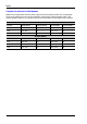
RIGOL Content Conventions in this Manual: DP800 series programmable linear DC power supply includes the following models. The programmable ranges of the voltage and current for each model are as listed below. Unless otherwise noted, in this manual, DP831A is taken as an example to illustrate the using method of each DP800 series command. DP831A Channel Voltage Range Voltage Default Current Range Current Default CH1 0V to 8.4V 0V 0A to 5.3A 5A CH2 0V to 32V 0V 0A to 2.
RIGOL Contents Guaranty and Declaration ......................................................................................................... I Safety Requirement .................................................................................................................. II General Safety Summary ............................................................................................................. II Safety Terms and Symbols .................................................................
RIGOL :MEMory[:STATe]:LOCK .................................................................................................... 2-19 :MEMory[:STATe]:STORe ................................................................................................... 2-19 :MEMory[:STATe]:VALid? ................................................................................................... 2-20 :MMEMory Commands .........................................................................................................
RIGOL :SYSTem:BEEPer:STATe .................................................................................................... 2-52 :SYSTem:BRIGhtness ....................................................................................................... 2-52 :SYSTem:COMMunicate:GPIB:ADDRess ............................................................................. 2-53 :SYSTem:COMMunicate:LAN:APPLy ...................................................................................
RIGOL :TRIGger:OUT:POLArity..................................................................................................... 2-79 :TRIGger:OUT:SIGNal ....................................................................................................... 2-80 :TRIGger:OUT:SOURce ..................................................................................................... 2-80 Chapter 3 Application Examples ........................................................................................
Chapter 1 Programming Overview RIGOL Chapter 1 Programming Overview This chapter introduces how to build the remote communication between the PC and instrument and provides an overview of the syntax, symbol, parameter type and abbreviation rules of the SCPI commands.
RIGOL Chapter 1 Programming Overview To Build Remote Communication You can build the remote communication between DP800 and PC over USB, LAN, RS232 or GPIB (option, can be extended via the USB-GPIB interface converter) interface. Note: the end mark of the command sent through RS232 interface is "\r\n". Operation Steps: 1 Install the Ultra Sigma common PC software Download the Ultra Sigma common PC software from www.rigol.com and install it according to the instructions.
Chapter 1 Programming Overview RIGOL (4) Use the GPIB interface: Connect the USB-GPIB interface converter to the USB Device interface at the rear panel of DP800 to extend a GPIB interface. Connect the instrument with your PC using GPIB cable. Press Utility I/O GPIB to set the GPIB address of the instrument. 3 Check whether the connection is successful Run the Ultra Sigma, search for resource, right-click the resource name and select “SCPI Panel Control” in the pop-up menu.
RIGOL Chapter 1 Programming Overview Remote Control Methods 1 User-defined Programming You can program and control the instrument using the SCPI (Standard Commands for Programmable Instruments) commands listed in chapter 2 Command System in various development environments (such as Visual C++, Visual Basic and LabVIEW). For details, refer to the introductions in chapter 4 Programming Demos.
Chapter 1 Programming Overview RIGOL Symbol Description The following four symbols are not the content of SCPI commands and will not be sent with the commands. They are usually used to describe the parameters in the commands. 1 Braces { } Usually, multiple optional parameters are enclosed in the braces and one of the parameters must be selected when sending the command. For example, :DISPlay:MODE {NORMal|WAVE|DIAL}.
RIGOL Chapter 1 Programming Overview Besides, many commands contain the MINimum and MAXimum parameters which are used to set the parameter to its minimum or maximum value. For example, MINimum and MAXimum in the :SYSTem:BRIGhtness {|MINimum|MAXimum} command are used to set the brightness to the minimum or maximum. Command Abbreviation All the commands are case-insensitive and you can use any of them. If abbreviation is used, all the capital letters in the command must be written completely.
Chapter 2 Command System RIGOL Chapter 2 Command System This chapter introduces the syntax, function, parameter and using instruction of each DP800 command in A-Z order. Main topics of this chapter: :ANALyzer Commands :APPLy Command :DELAY Commands :DISPlay Command IEEE488.
RIGOL Chapter 2 Command System :ANALyzer Commands The :ANALyzer commands are used to set the analyzer parameters, execute analysis and query the analysis results.
RIGOL Chapter 2 Command System :ANALyzer:ENDTime Syntax :ANALyzer:ENDTime {|MINimum|MAXimum} :ANALyzer:ENDTime? [MINimum|MAXimum] Description Set the end time of the analyzer. Query the end time of the analyzer. Parameter Explanation Return Format Example Related Commands Name Type Range Default Integer Start time to the current maximum record time 2 You can only set the end time when valid record file is opened (refer to the :ANALyzer:FILE? command).
RIGOL Chapter 2 Command System :ANALyzer:MMEMory Syntax Description Parameter Explanation Example :ANALyzer:MMEMory Open the specified record file. Name Type Range Default ASCII character string Valid directory under D disk None This command is only available when valid record file is stored in the specified location. :ANAL:MMEMory D:\record.ROF /*Open the record.
RIGOL Chapter 2 Command System :ANALyzer:STARTTime Syntax :ANALyzer:STARTTime {|MINimum|MAXimum} :ANALyzer:STARTTime? [MINimum|MAXimum] Description Set the start time of the analyzer. Query the start time of the analyzer. Parameter Explanation Return Format Example Name Type Range Default Integer 1s to end time 1 You can only set the start time when valid record file is opened (refer to the :ANALyzer:FILE? command).
RIGOL Chapter 2 Command System :APPLy Command The :APPLy command provides the most straightforward method to program the power supply over the remote interface. Syntax :APPLy {CH1|CH2|CH3} [,|MINimum|MAXimum][,|MINimum|MAXimum] :APPLy? {CH1|CH2|CH3}[,CURRent|VOLTage] Description Set the voltage/current of the specified channel. Query the voltage/current of the specified channel.
RIGOL Chapter 2 Command System :DELAY Commands The :DELAY commands are used to set the delayer parameters (the number of groups, number of cycles, end state and etc) as well as enable or disable the delayer. Command List: :DELAY:CYCLEs :DELAY:ENDState :DELAY:GROUPs :DELAY:PARAmeter :DELAY[:STATe] :DELAY:STATe:GEN :DELAY:STOP :DELAY:TIME:GEN :DELAY:CYCLEs Syntax :DELAY:CYCLEs {N|I}[,] :DELAY:CYCLEs? Description Set the number of cycles of the delayer.
RIGOL Chapter 2 Command System :DELAY:ENDState Syntax :DELAY:ENDState {ON|OFF|LAST} :DELAY:ENDState? Description Set the end state of the delayer to On, Off or Last. Query the end state of the delayer. Parameter Explanation Return Format Example Name Type Range Default {ON|OFF|LAST} Discrete ON|OFF|LAST OFF The end state refers to the state of the instrument when the delayer stops.
RIGOL Chapter 2 Command System :DELAY:PARAmeter Syntax :DELAY:PARAmeter ,{ON|OFF},
RIGOL Chapter 2 Command System :DELAY:STATe:GEN Syntax :DELAY:STATe:GEN {01P|10P} :DELAY:STATe:GEN? Description Select the pattern used when generating state automatically. Query the pattern used when generating state automatically. Parameter Explanation Return Format Example Name Type Range Default {01P|10P} Discrete 01P|10P 01P 01P: 0 1 pattern. The state is set to “Off” and “On” alternately. 10P: 1 0 pattern. The state is set to “On” and “Off” alternately.
RIGOL Chapter 2 Command System :DELAY:TIME:GEN Syntax :DELAY:TIME:GEN {FIX|INC|DEC}[,[,]] :DELAY:TIME:GEN? Description Set the method used to generate time automatically as well as the corresponding on/off delay time or the time base value and step value. Query the method used to generate time automatically as well as the corresponding parameters.
RIGOL Chapter 2 Command System :DISPlay Command Syntax :DISPlay:MODE {NORMal|WAVE|DIAL} :DISPlay:MODE? Description Set the display mode to normal, wave or dial. Query the current display mode. Parameter Explanation Return Format Example Name Type Range Default {NORMal|WAVE|DIAL} Discrete NORMal|WAVE|DIAL NORMal NORMal: normal mode. The parameters (such as the voltage and current) of all the channels are displayed in number format. WAVE: waveform mode.
RIGOL Chapter 2 Command System IEEE488.2 Common Commands Command List: *IDN? *RCL *RST *SAV *TST? *IDN? Syntax Description Return Format *IDN? Query the ID character string of the instrument. The query returns the ID character string of the instrument, for example, RIGOL TECHNOLOGIES,DP831A,DP8A000001,00.01.01. *RCL Syntax Description *RCL {1|2|3|4|5|6|7|8|9|10} Read the instrument state stored.
RIGOL Chapter 2 Command System *SAV Syntax Description *SAV {1|2|3|4|5|6|7|8|9|10} Save the current system state to the specified storage location using the default name. The default name is RIGOLn.RSF; n corresponds to the number of the storage location. Parameter Explanation Example Related Command Name Type Range Default {1|2|3|4|5|6|7|8|9|10} Discrete 1|2|3|4|5|6|7|8|9|10 None The power supply provides 10 storage locations (numbered 1 to 10) for instrument states.
RIGOL Chapter 2 Command System :INSTrument Commands Command List: :INSTrument:NSELect :INSTrument[:SELEct] :INSTrument:NSELect Syntax :INSTrument:NSELect {1|2|3} :INSTrument:NSELect? Description Select the desired channel. Query the channel currently selected. Parameter Explanation Return Format Example Related Command Name Type Range Default {1|2|3} Discrete 1|2|3 1 In this command, numbers are used in place of the channel labels in the :INSTrument[:SELEct] command.
RIGOL Chapter 2 Command System :MEASure Commands Command List: :MEASure:ALL[:DC]? :MEASure:CURRent[:DC]? :MEASure:POWEr[:DC]? :MEASure[:VOLTage][:DC]? :MEASure:ALL[:DC]? Syntax Description :MEASure:ALL[:DC]? [{CH1|CH2|CH3}] Query the voltage, current and power measured internally on the specified channel.
RIGOL Chapter 2 Command System :MEASure:POWEr[:DC]? Syntax Description :MEASure:POWEr[:DC]? [{CH1|CH2|CH3}] Query the output power measured internally on the specified channel. Parameter Explanation Return Format Example Related Commands Name Type Range Default [{CH1|CH2|CH3}] Discrete CH1|CH2|CH3 None If the parameter is omitted, the command queries the power of the channel currently selected.
RIGOL Chapter 2 Command System :MEMory Commands The :MEMory commands are used to save, delete, read or lock the file stored in the specified storage location in the internal memory. DP800 allows four kinds of files to be saved in the internal memory. 1. State File (RSF): store the current system state, including the voltage, current, OVP, OCP and track function status of each channel as well as the system parameters.
RIGOL Chapter 2 Command System :MEMory[:STATe]:LOCK Syntax :MEMory[:STATe]:LOCK {RSF|ROF|RTF|RDF},{1|2|3|4|5|6|7|8|9|10},{ON|OFF} :MEMory[:STATe]:LOCK? {RSF|ROF|RTF|RDF},{1|2|3|4|5|6|7|8|9|10} Description Lock or unlock the file in the specified storage location. Query whether the file in the specified storage location is locked.
RIGOL Chapter 2 Command System :MEMory[:STATe]:VALid? Syntax Description Parameter Explanation Return Format Example 2-20 :MEMory[:STATe]:VALid? {RSF|ROF|RTF|RDF},{1|2|3|4|5|6|7|8|9|10} Query whether the specified storage location contains a valid file. Name Type Range Default {RSF|ROF|RTF|RDF} Discrete RSF|ROF|RTF|RDF None {1|2|3|4|5|6|7|8|9|10} Discrete 1|2|3|4|5|6|7|8|9|10 None The read and delete operations are only available when the specified storage location contains a valid file.
Chapter 2 Command System RIGOL :MMEMory Commands The :MMEMory commands are used to store the file to the specified external storage directory, read or delete the specified file in the external memory as well as query the disk information of the external memory.
RIGOL Chapter 2 Command System :MMEMory:CDIRectory Syntax :MMEMory:CDIRectory :MMEMory:CDIRectory? Description Set the current operation directory. Query the current operation directory. Parameter Explanation Return Format Example Related Commands Name Type Range Default ASCII character string Valid directory NULL This command is only applicable to external memory. If the directory set does not exist, “Invalid directory.” will be displayed.
RIGOL Chapter 2 Command System :MMEMory:DISK? Syntax :MMEMory:DISK? Description Query the drive letter available of the power supply. Explanation This command only queries the drive letter of the external memory of the power supply. Return Format Example The query returns the drive letter available, for example, D:\.
RIGOL Chapter 2 Command System :MMEMory:STORe Syntax Description :MMEMory:STORe Save the file with the specified filename under the current operation directory. Parameter Explanation Example 2-24 Name Type Range Default ASCII character string Filename of the file to be saved, including Chinese characters, English characters or numbers None With this command, you can save the state file (RSF), timer file (RTF) and delay file (RDF).
RIGOL Chapter 2 Command System :MONItor Commands The :MONItor commands are used to set the monitor condition and stop mode of the monitor as well as enable or disable the monitor.
RIGOL Chapter 2 Command System :MONItor:CURRent[:VALue] Syntax :MONItor:CURRent[:VALue] {|MINimum|MAXimum} :MONItor:CURRent[:VALue]? [MINimum|MAXimum] Description Set the current of the monitor condition. Query the current of the monitor condition. Parameter Return Format Example Related Commands Name Type Range Default Real 0 to the maximum current of the current channel 0.
RIGOL Chapter 2 Command System :MONItor:POWER[:VALue] Syntax :MONItor:POWER[:VALue] {|MINimum|MAXimum} :MONItor:POWER[:VALue]? [MINimum|MAXimum] Description Set the power of the monitor condition. Query the power of the monitor condition. Parameter Return Format Example Name Type Range Default Real 0 to the maximum power of the current channel 0.25*rated power of the current channel The query returns the power of the current monitor condition, for example, 20.000.
RIGOL Chapter 2 Command System :MONItor:STOPway Syntax :MONItor:STOPway {OUTOFF|WARN|BEEPER|NONE},{ON|OFF} :MONItor:STOPway? Description Set the stop mode of the monitor. Multiple stop modes can be enabled at the same time. Query the stop mode of the monitor.
RIGOL Chapter 2 Command System :MONItor:VOLTage:CONDition Syntax :MONItor:VOLTage:CONDition {V|NONE},{AND|OR|NONE} :MONItor:VOLTage:CONDition? Description Set the voltage monitor condition of the monitor. Query the voltage monitor condition of the monitor.
RIGOL Chapter 2 Command System :MONItor:VOLTage[:VALue] Syntax :MONItor:VOLTage[:VALue] {|MINimum|MAXimum} :MONItor:VOLTage[:VALue]? [MINimum|MAXimum] Description Set the voltage of the monitor condition. Query the voltage of the monitor condition. Parameter Return Format Example Related Commands Name Type Range Default Real 0 to the maximum voltage of the current channel 0.
RIGOL Chapter 2 Command System :OUTPut Commands Command List: :OUTPut:MODE? :OUTPut:OCP:CLEAR :OUTPut:OCP:QUES? :OUTPut:OCP[:STATe] :OUTPut:OCP:VALue :OUTPut:OVP:CLEAR :OUTPut:OVP:QUES? :OUTPut:OVP[:STATe] :OUTPut:OVP:VALue :OUTPut[:STATe] :OUTPut:TRACk :OUTPut:MODE? Syntax Description :OUTPut:MODE? {CH1|CH2|CH3} Query the current output mode of the specified channel.
RIGOL Chapter 2 Command System :OUTPut:OCP:QUES? Syntax Description Parameter Explanation Return Format Example Related Commands :OUTPut:OCP:QUES? {CH1|CH2|CH3} Query whether overcurrent protection occurs to the specified channel currently, namely the output current exceeds the overcurrent protection limit and the output turns off automatically.
RIGOL Chapter 2 Command System :OUTPut:OCP:VALue Syntax :OUTPut:OCP:VALue {CH1|CH2|CH3},{|MINimum|MAXimum} :OUTPut:OCP:VALue? {CH1|CH2|CH3}[,MINimum|MAXimum] Description Set the overcurrent protection limit of the specified channel. Query the overcurrent protection limit of the specified channel.
RIGOL Chapter 2 Command System :OUTPut:OVP:QUES? Syntax Description Parameter Explanation Return Format Example Related Command :OUTPut:OVP:QUES? {CH1|CH2|CH3} Query whether overvoltage protection occurs to the specified channel, namely the output voltage exceeds the overvoltage protection limit and the output turns off automatically.
RIGOL Chapter 2 Command System :OUTPut:OVP:VALue Syntax :OUTPut:OVP:VALue {CH1|CH2|CH3},{|MINimum|MAXimum} :OUTPut:OVP:VALue? {CH1|CH2|CH3}[,MINimum|MAXimum] Description Set the overvoltage protection limit of the specified channel. Query the overvoltage protection limit of the specified channel.
RIGOL Chapter 2 Command System :OUTPut:TRACk Syntax :OUTPut:TRACk {CH1|CH2|CH3},{ON|OFF} :OUTPut:TRACk? [{CH1|CH2|CH3}] Description Enable or disable the track function of the specified channel. Query the status of the track function of the specified channel.
Chapter 2 Command System RIGOL :PRESet Commands Command List: :PRESet[:APPLy] :PRESet:KEY :PRESet:USER[n]:SET:CURRent :PRESet:USER[n]:SET:DEFault :PRESet:USER[n]:SET:TRACk :PRESet:USER[n]:SET:OCP :PRESet:USER[n]:SET:OVP :PRESet:USER[n]:SET:OTP :PRESet:USER[n]:SET:SURE :PRESet:USER[n]:SET:VOLTage Note: When [n] is omitted, the operation is performed on the user-preset state currently selected by default.
RIGOL Chapter 2 Command System :PRESet:KEY Syntax :PRESet:KEY {DEFAULT|USER1|USER2|USER3|USER4} :PRESet:KEY? Description Define the setting recalled by Preset at the front panel. Query the setting recalled by Preset at the front panel. Parameter Name {DEFAULT|USER1|USER2| USER3|USER4} Explanation Return Format Example Type Discrete Range Default DEFAULT|USER1|USER2| USER3|USER4 DEFAULT DP800 supports to restore the instrument to default state or user-preset state (up to 4 kinds).
RIGOL Chapter 2 Command System :PRESet:USER[n]:SET:CURRent Syntax :PRESet:USER[n]:SET:CURRent {|MINimum|MAXimum} :PRESet:USER[n]:SET:CURRent? [MINimum|MAXimum] Description Set the current of the specified user-preset state. Query the current of the specified user-preset state.
RIGOL Chapter 2 Command System :PRESet:USER[n]:SET:TRACk Syntax :PRESet:USER[n]:SET:TRACk {ON|OFF} :PRESet:USER[n]:SET:TRACk? Description Enable or disable the track function of the specified user-preset state. Query the status of the track function of the specified user-preset state. Parameter Explanation Return Format Example Name Type Range Default [n] Discrete 1|2|3|4 None {ON|OFF} Bool ON|OFF OFF By default, this command sets the parameter of the channel currently selected.
RIGOL Chapter 2 Command System :PRESet:USER[n]:SET:OVP Syntax :PRESet:USER[n]:SET:OVP {ON|OFF}[,|MINimum|MAXimum] :PRESet:USER[n]:SET:OVP? [MINimum|MAXimum] Description Enable or disable the overvoltage protection function of the specified user-preset state and set the overvoltage protection limit. Query the status and limit of the overvoltage protection function of the specified user-preset state.
RIGOL Chapter 2 Command System :PRESet:USER[n]:SET:SURE Syntax Description :PRESet:USER[n]:SET:SURE Confirm the setting of the specified user-preset state. Parameter Name Type Range Default [n] Discrete 1|2|3|4 None :PRESet:USER[n]:SET:VOLTage Syntax :PRESet:USER[n]:SET:VOLTage |MINimum|MAXimum} :PRESet:USER[n]:SET:VOLTage? [MINimum|MAXimum] Description Set the voltage of the specified user-preset state. Query the voltage of the specified user-preset state.
RIGOL Chapter 2 Command System :RECorder Commands Command List: :RECorder:DESTination? :RECorder:MEMory :RECorder:MMEMory :RECorder:PERIod :RECorder[:STATe] :RECorder:DESTination? Syntax :RECorder:DESTination? Description Query the storage directory of the record file. Explanation Before enabling the recorder, use the :RECorder:MEMory or :RECorder:MMEMory command to set the storage directory.
RIGOL Chapter 2 Command System :RECorder:MMEMory Syntax Description :RECorder:MMEMory Set the storage directory of the record file to a directory of the external memory. Parameter Explanation Example Related Commands Name Type Range Default ASCII character string Directory of the external memory None This command is only available when an USB storage device is connected to the power supply.
RIGOL Chapter 2 Command System :RECorder[:STATe] Syntax :RECorder[:STATe] {ON|OFF} :RECorder[:STATe]? Description Enable or disable the recorder. Query the status of the recorder. Parameter Explanation Return Format Example Related Commands Name Type Range Default {ON|OFF} Bool ON|OFF OFF When the recorder is enabled, you cannot set the record period and storage directory.
RIGOL Chapter 2 Command System :SOURce Commands The :SOURce commands are used to set the voltage, current, OVP and OCP of the specified channel. Their functions are equivalent to that of :APPLy Command. Although the :APPLy command provides the most straightforward method to program the power supply over the remote interfaces, the :SOURce commands give you more flexibility to change individual parameters.
RIGOL Chapter 2 Command System [:SOURce[n]]:CURRent:PROTection[:LEVel] Syntax [:SOURce[n]]:CURRent:PROTection[:LEVel] {|MINimum|MAXimum} [:SOURce[n]]:CURRent:PROTection[:LEVel]? [{MINimum|MAXimum}] Description Set the overcurrent protection limit of the specified channel. Query the overcurrent protection limit of the specified channel.
RIGOL Chapter 2 Command System [:SOURce[n]]:CURRent:PROTection:STATe Syntax [:SOURce[n]]:CURRent:PROTection:STATe {ON|OFF} [:SOURce[n]]:CURRent:PROTection:STATe? Description Enable or disable the overcurrent protection function of the specified channel. Query the status of the overcurrent protection function of the specified channel.
RIGOL Chapter 2 Command System [:SOURce[n]]:VOLTage:PROTection[:LEVel] Syntax [:SOURce[n]]:VOLTage:PROTection[:LEVel] {|MINimum|MAXimum} [:SOURce[n]]:VOLTage:PROTection[:LEVel]? [{MINimum|MAXimum}] Description Set the overvoltage protection limit of the specified channel. Query the overvoltage protection limit of the specified channel.
RIGOL Chapter 2 Command System [:SOURce[n]]:VOLTage:PROTection:STATe Syntax [:SOURce[n]]:VOLTage:PROTection:STATe {ON|OFF} [:SOURce[n]]:VOLTage:PROTection:STATe? Description Enable or disable the overvoltage protection function of the specified channel. Query the status of the overvoltage protection function of the specified channel.
Chapter 2 Command System RIGOL :SYSTem Commands Command List: :SYSTem:BEEPer[:IMMediate] :SYSTem:BEEPer:STATe :SYSTem:BRIGhtness :SYSTem:COMMunicate:GPIB:ADDRess :SYSTem:COMMunicate:LAN:APPLy :SYSTem:COMMunicate:LAN:AUTOip[:STATe] :SYSTem:COMMunicate:LAN:DHCP[:STATe] :SYSTem:COMMunicate:LAN:DNS :SYSTem:COMMunicate:LAN:GATEway :SYSTem:COMMunicate:LAN:IPADdress :SYSTem:COMMunicate:LAN:MAC? :SYSTem:COMMunicate:LAN:MANualip[:STATe] :SYSTem:COMMunicate:LAN:SMA
RIGOL Chapter 2 Command System :SYSTem:BEEPer[:IMMediate] Syntax Description Example :SYSTem:BEEPer[:IMMediate] Send this command and the beeper sounds. :SYST:BEEP :SYSTem:BEEPer:STATe Syntax :SYSTem:BEEPer:STATe {ON|OFF} :SYSTem:BEEPer:STATe? Description Enable or disable the beeper. Query the status of the beeper.
RIGOL Chapter 2 Command System :SYSTem:COMMunicate:GPIB:ADDRess Syntax :SYSTem:COMMunicate:GPIB:ADDRess :SYSTem:COMMunicate:GPIB:ADDRess? Description Set the GPIB address. Query the current GPIB address. Parameter Explanation Return Format Example Name Type Range Default Integer 0 to 30 2 Before using the GPIB interface, extend a GPIB interface using the USB-GPIB interface converter; then, connect the instrument and PC using GPIB cable and set the GPIB address.
RIGOL Chapter 2 Command System :SYSTem:COMMunicate:LAN:DHCP[:STATe] Syntax :SYSTem:COMMunicate:LAN:DHCP[:STATe] {ON|OFF} :SYSTem:COMMunicate:LAN:DHCP[:STATe]? Description Enable or disable the DHCP mode. Query the status of the DHCP mode. Parameter Explanation Return Format Example Name Type Range Default {ON|OFF} Bool ON|OFF ON In DHCP mode, the DHCP server in the current network assigns network parameters (such as the IP address) for the instrument.
RIGOL Chapter 2 Command System :SYSTem:COMMunicate:LAN:GATEway Syntax :SYSTem:COMMunicate:LAN:GATEway :SYSTem:COMMunicate:LAN:GATEway? Description Set the default gateway. Query the current default gateway. Parameter Explanation Return Format Example Name Type Range Default ASCII character string The format is nnn.nnn.nnn.
RIGOL Chapter 2 Command System :SYSTem:COMMunicate:LAN:MAC? Syntax :SYSTem:COMMunicate:LAN:MAC? Description Query the MAC address. Explanation The MAC (Media Access Control) address is also called hardware address and is used to define the location of the network device. For a power supply, the MAC address is unique and is usually used to recognize the instrument when assigning IP address for the instrument.
RIGOL Chapter 2 Command System :SYSTem:COMMunicate:LAN:SMASK Syntax :SYSTem:COMMunicate:LAN:SMASK :SYSTem:COMMunicate:LAN:SMASK? Description Set the subnet mask. Query the current subnet mask. Parameter Explanation Return Format Example Name Type Range Default ASCII character string The format is nnn.nnn.nnn.nnn; wherein, the range of nnn is from 0 to 255 None This command is only available when the manual IP configuration mode is enabled.
RIGOL Chapter 2 Command System :SYSTem:COMMunicate:RS232:DATABit Syntax :SYSTem:COMMunicate:RS232:DATABit {5|6|7|8} :SYSTem:COMMunicate:RS232:DATABit? Description Set the data bit of the RS232 interface. Query the data bit of the RS232 interface. Parameter Return Format Example Name Type Range Default {5|6|7|8} Discrete 5|6|7|8 8 The query returns 5, 6, 7 or 8.
RIGOL Chapter 2 Command System :SYSTem:COMMunicate:RS232:STOPBit Syntax :SYSTem:COMMunicate:RS232:STOPBit {1|2} :SYSTem:COMMunicate:RS232:STOPBit? Description Set the stop bit to 1 or 2. Query the current stop bit. Parameter Return Format Example Name Type Range Default {1|2} Discrete 1|2 1 The query returns 1 or 2.
RIGOL Chapter 2 Command System :SYSTem:LANGuage:TYPE Syntax :SYSTem:LANGuage:TYPE {EN|CH} :SYSTem:LANGuage:TYPE? Description Set the system language to English or Chinese. Query the system language. Parameter Return Format Example Name Type Range Default {EN|CH} Discrete EN|CH CH The query returns English or Chinese. :SYST:LANG:TYPE EN :SYST:LANG:TYPE? :SYSTem:LOCal Syntax :SYSTem:LOCal Description The power supply returns from remote mode to local mode.
RIGOL Chapter 2 Command System :SYSTem:OTP Syntax :SYSTem:OTP {ON|OFF} :SYSTem:OTP? Description Enable or disable the over-temperature protection (OTP) function. Query the status of the over-temperature protection function. Parameter Explanation Return Format Example Name Type Range Default {ON|OFF} Bool ON|OFF ON When the OTP function is enabled, the instrument turns off the output automatically when the temperature inside the instrument reaches the limit. The query returns ON or OFF.
RIGOL Chapter 2 Command System :SYSTem:SAVer Syntax :SYSTem:SAVer {ON|OFF} :SYSTem:SAVer? Description Enable or disable the screen saver function. Query the status of the screen saver function. Parameter Explanation Return Format Example Name Type Range Default {ON|OFF} Bool ON|OFF OFF When the screen saver function is enabled, the instrument will enter the screen saver mode automatically after standing by for 25 minutes and will enter the black screen state after another 12.5 minutes.
Chapter 2 Command System RIGOL :TIMEr Commands Command List: :TIMEr:CYCLEs :TIMEr:ENDState :TIMEr:GROUPs :TIMEr:PARAmeter :TIMEr[:STATe] :TIMEr:TEMPlet:CONSTruct :TIMEr:TEMPlet:FALLRate :TIMEr:TEMPlet:INTErval :TIMEr:TEMPlet:INVErt :TIMEr:TEMPlet:MAXValue :TIMEr:TEMPlet:MINValue :TIMEr:TEMPlet:OBJect :TIMEr:TEMPlet:PERIod :TIMEr:TEMPlet:POINTs :TIMEr:TEMPlet:RISERate :TIMEr:TEMPlet:SELect :TIMEr:TEMPlet:SYMMetry :TIMEr:TEMPlet:WIDTh D
RIGOL Chapter 2 Command System :TIMEr:CYCLEs Syntax :TIMEr:CYCLEs {N|I}[,] :TIMEr:CYCLEs? Description Set the number of cycles of the timer. Query the current number of cycles of the timer. Parameter Explanation Name Type Range Default {N|I} Discrete N|I N Integer 1 to 99999 1 The number of cycles is defined as the number of times that the instrument performs timing output according to the preset voltage/current.
RIGOL Chapter 2 Command System :TIMEr:ENDState Syntax :TIMEr:ENDState {OFF|LAST} :TIMEr:ENDState? Description Set the end state of the timer to “Off” or “Last”. Query the current end state of the timer. Parameter Explanation Return Format Example Name Type Range Default {OFF|LAST} Discrete OFF|LAST OFF The end state refers to the state of the instrument after it finishes outputting the total number of groups of voltage/current values when the number of cycles is a specified value.
RIGOL Chapter 2 Command System :TIMEr:GROUPs Syntax :TIMEr:GROUPs :TIMEr:GROUPs? Description Set the number of output groups of the timer. Query the current number of output groups of the timer. Parameter Explanation Name Type Range Default Integer 1 to 2048 1 The number of groups is defined as the number of groups of preset voltage/current values that the power supply outputs in each cycle.
RIGOL Chapter 2 Command System :TIMEr:PARAmeter Syntax :TIMEr:PARAmeter ,,,
RIGOL Chapter 2 Command System :TIMEr[:STATe] Syntax :TIMEr[:STATe] {ON|OFF} :TIMEr[:STATe]? Description Enable or disable the timing output function. Query the status of the timing output function. Parameter Explanation Return Format Example Name Type Range Default {ON|OFF} Bool ON|OFF OFF Enabling the timer will change the output state of the channel; make sure that the change in the output state will not affect the device connected to the power supply before enabling the timer.
RIGOL Chapter 2 Command System :TIMEr:TEMPlet:INTErval Syntax :TIMEr:TEMPlet:INTErval :TIMEr:TEMPlet:INTErval? Description Set the time interval. Query the current time interval. Parameter Explanation Return Format Example Name Type Range Default Integer 1 to 99999 1 The interval refers to the time required for the instrument to output each group of timer parameters created using the templet currently selected. The query returns an integer from 1 to 99999, for example, 15.
RIGOL Chapter 2 Command System :TIMEr:TEMPlet:MAXValue Syntax :TIMEr:TEMPlet:MAXValue {|MINimum|MAXimum} :TIMEr:TEMPlet:MAXValue? [MINimum|MAXimum] Description Set the maximum voltage or current of the templet currently selected. Query the maximum voltage or current of the templet currently selected.
RIGOL Chapter 2 Command System :TIMEr:TEMPlet:OBJect Syntax :TIMEr:TEMPlet:OBJect {V|C}[,|MINimum|MAXimum] :TIMEr:TEMPlet:OBJect? [MINimum|MAXimum] Description Select the editing object of the templet and set the current or voltage. Query the editing object of the templet as well as the corresponding current or voltage.
RIGOL Chapter 2 Command System :TIMEr:TEMPlet:POINTs Syntax :TIMEr:TEMPlet:POINTs :TIMEr:TEMPlet:POINTs? Description Set the total number of points. Query the total number of points. Parameter Explanation Return Format Example Name Type Range Default Integer 10 to 2048 10 The total number of points refers to the number of groups of timer parameters created using the templet currently selected.
RIGOL Chapter 2 Command System :TIMEr:TEMPlet:SELect Syntax :TIMEr:TEMPlet:SELect {SINE|SQUARE|RAMP|UP|DN|UPDN|RISE|FALL} :TIMEr:TEMPlet:SELect? Description Select the desired templet. Query the templet currently selected. Parameter Return Format Example Name Type Range Default {SINE|SQUARE|RAMP| UP|DN|UPDN|RISE|FALL} Discrete SINE|SQUARE|RAMP| UP|DN|UPDN|RISE|FALL SINE The query returns SINE, SQUARE, RAMP, UP, DN, UPDN, RISE or FALL.
RIGOL Chapter 2 Command System :TRIGger Commands Command List: :TRIGger:IN[:ENABle] :TRIGger:IN:RESPonse :TRIGger:IN:SENSitivity :TRIGger:IN:SOURce :TRIGger:IN:TYPE :TRIGger:OUT:CONDition :TRIGger:OUT:DUTY :TRIGger:OUT[:ENABle] :TRIGger:OUT:PERIod :TRIGger:OUT:POLArity :TRIGger:OUT:SIGNal :TRIGger:OUT:SOURce :TRIGger:IN[:ENABle] Syntax :TRIGger:IN[:ENABle] [D0|D1|D2|D3,]{ON|OFF} :TRIGger:IN[:ENABle]? [D0|D1|D2|D3] Description Enable or disable the trigger
RIGOL Chapter 2 Command System :TRIGger:IN:RESPonse Syntax :TRIGger:IN:RESPonse [D0|D1|D2|D3,]{ON|OFF|ALTER} :TRIGger:IN:RESPonse? [D0|D1|D2|D3] Description Set the output response of the trigger input of the specified data line. Query the output response of the trigger input of the specified data line.
RIGOL Chapter 2 Command System :TRIGger:IN:SOURce Syntax :TRIGger:IN:SOURce [D0|D1|D2|D3,][CH1[,CH2[,CH3]]] :TRIGger:IN:SOURce? [D0|D1|D2|D3] Description Set the source under control of the trigger input of the specified data line. Query the source under control of the trigger input of the specified data line.
RIGOL Chapter 2 Command System :TRIGger:OUT:CONDition Syntax :TRIGger:OUT:CONDition [D0|D1|D2|D3,]{OUTOFF|OUTON|>V|C|P||MINimum|MAXimum] :TRIGger:OUT:CONDition? [D0|D1|D2|D3][,MINimum|MAXimum] Description Set the trigger condition of the trigger output of the specified data line. Query the trigger condition of the trigger output of the specified data line.
RIGOL Chapter 2 Command System :TRIGger:OUT:DUTY Syntax :TRIGger:OUT:DUTY [D0|D1|D2|D3,] :TRIGger:OUT:DUTY? [D0|D1|D2|D3] Description Set the duty cycle of the square waveform of the trigger output on the specified data line. Query the duty cycle of the square waveform of the trigger output on the specified data line.
RIGOL Chapter 2 Command System :TRIGger:OUT:PERIod Syntax :TRIGger:OUT:PERIod [D0|D1|D2|D3,] :TRIGger:OUT:PERIod? [D0|D1|D2|D3] Description Set the period of the square waveform of the trigger output on the specified data line. Query the period of the square waveform of the trigger output on the specified data line. Parameter Explanation Return Format Example Name Type Range Default [D0|D1|D2|D3] Discrete D0|D1|D2|D3 D0 Real 0.0001 to 2.
RIGOL Chapter 2 Command System :TRIGger:OUT:SIGNal Syntax :TRIGger:OUT:SIGNal [D0|D1|D2|D3,]{LEVEL|SQUARE} :TRIGger:OUT:SIGNal? [D0|D1|D2|D3] Description Set the type of the trigger output signal of the specified data line. Query the type of the trigger output signal of the specified data line.
Chapter 3 Application Examples RIGOL Chapter 3 Application Examples This chapter provides some application examples of the SCPI commands. A series of SCPI commands are combined to realize the main functions of the power supply. Note: 1 The examples in this chapter are based on DP831A. For other models, the ranges of some parameters might be different. When using the commands, please make proper adjustment according to the model of your instrument.
RIGOL Chapter 3 Application Examples CV Output Requirement Use the SCPI commands to realize the following functions: CH1 CV output; set the output voltage to 5V, the output current to 5A and the overcurrent protection limit to 5.3A. Method 1 1 *IDN? 2 3 4 5 6 7 /*Query the ID character string of the power supply to check whether the remote communication is normal*/ :INST CH1 /*Select CH1*/ :CURR 5 /*Set the current to 5A*/ :CURR:PROT 5.3 /*Set the overcurrent protection limit of CH1 to 5.
Chapter 3 Application Examples RIGOL Timing Output Requirement Use the SCPI commands to realize the following functions: Set the timer parameters of CH1: set the number of groups to 25, the number of cycles to 20 and the end state to last; use the Sine templet to create the timer parameters; set the editing object to voltage and the current to 2A; set the templet maximum to 8V and the templet minimum to 0V; set the total number of points to 25 and the time interval to 5s; enable the invert.
RIGOL Chapter 3 Application Examples To Use the Recorder Requirement Use the SCPI commands to realize the following functions: Set the record period to 2s and the storage directory of the record file to C:\REC 1:RIGOL.ROF; enable the recorder, wait for about 2 minutes and disable the recorder.
RIGOL Chapter 3 Application Examples To Use the Monitor Requirement Use the SCPI commands to realize the following functions: Monitor CH1. Set the monitor condition: >Volt, >Curr or >Power; set the voltage to 5V, the current to 3A and the power to 15W; set the stop mode to OutpOff, Warning and Beeper. Enable the monitor.
RIGOL Chapter 3 Application Examples To Use the Trigger Trigger Input Requirement Use the SCPI commands to realize the following functions: Set the trigger input parameters of D0: set the source under control to CH1, the trigger type to falling edge, the output response to OutpOpen and the trigger sensitivity to low. Enable the trigger input function of D0.
Chapter 4 Programming Demos RIGOL Chapter 4 Programming Demos This chapter provides the demos for programming and controlling the power supply using SCPI commands under Excel, Matlab, LabVIEW, Visual Basic and Visual C++ environment on the basis of NI-VISA. NI-VISA (National Instrument-Virtual Instrument Software Architecture) is an advanced application programming interface developed by NI (National Instrument) for communicating with various instrument buses.
RIGOL Chapter 4 Programming Demos Programming Preparations Before programming, you need to make the following preparations: 1 Make sure that your PC has installed the NI-VISA library (can be downloaded from NI website: http://www.ni.com/visa/). Here, the default installation path is C:\Program Files\IVI Foundation\VISA.
Chapter 4 Programming Demos RIGOL Excel Programming Demo The program used in this demo: Microsoft Excel 2010 The function realized in this demo: send the *IDN? Command to read the device information. 1 Create a new Excel file that enables the Macros. In this demo, the file is named as DP800_Demo_Excel.xlsm. 2 Run the DP800_Demo_Excel.xlsm file. Click File→Options at the upper-left corner of the Excel file to open the interface as shown in the figure below.
RIGOL 4 Chapter 4 Programming Demos Select Tools(T) in the Microsoft Visual Basic menu bar and click References. Select VISA Library in the pop-up dialog box and click OK to refer to the VISA Library. Explanation: If you cannot find VISA Library in the list at the left of the figure above, please follow the method below to find it. (1) Make sure that your PC has installed the NI-VISA library. (2) Click Browse… at the right and set the search range to C:\WINDOWS\system32 and the filename to visa32.
Chapter 4 Programming Demos 5 RIGOL Click View Code in the Developer menu to enter the Microsoft Visual Basic interface. Add the following codes and save the file. Note: If the Excel file created at step 2 does not enable the Macros, at this point, the prompt message “The following features cannot be saved in macro-free workbooks”will be displayed. In this situation, please save the Excel file as a file using the Macros.
RIGOL 7 4-6 Chapter 4 Programming Demos Click *IDN? to run the program.
RIGOL Chapter 4 Programming Demos Matlab Programming Demo The program used in this demo: MATLAB R2009a The function realized in this demo: read the output voltage, current and power measured internally on CH1. 1 Run the Matlab software and modify the current directory (namely modify the Current Directory at the top of the software). In this demo, the current directory is modified to E:\DP800_Demo. 2 Click File New Blank M-File in the Matlab interface to create an empty M file.
RIGOL Chapter 4 Programming Demos LabVIEW Programming Demo The program used in this demo: LabVIEW 2009 The functions realized in this demo: search for the instrument address, connect the instrument, send command and read the return value. 1 Run LabVIEW 2009, create a VI file and name it as DP800_Demo_LABVIEW. 2 Add controls in the front panel interface, including the Address bar, Command bar and Return bar as well as the Connect, Write, Read and Exit buttons.
Chapter 4 Programming Demos 4 RIGOL Add events, including connecting instrument, write operation, read operation and exit.
RIGOL Chapter 4 Programming Demos (3) Read operation (including error processing): 4-10 DP800 Programming Guide
Chapter 4 Programming Demos RIGOL (4) Exit: 5 Run the program and the interface as shown in the figure below is displayed. Click the Address dropdown box and select the VISA resource name; click Connect to connect the instrument; enter the command into the Command textbox and click Write to write the command into the instrument. If the command is a query command, click Read and the return value is displayed in the Return textbox.
RIGOL Chapter 4 Programming Demos Visual Basic Programming Demo The program used in this demo: Visual Basic 6.0 The function realized in this demo: enable the three channels of the power supply and show the colors of the channels. 1 Build a standard application program project (Standard EXE) and name it as DP800_Demo_VB. 2 Click the Existing tab of ProjectAdd Module. Search for the visa32.bas file in the include folder under the NI-VISA installation path and add the file.
Chapter 4 Programming Demos RIGOL Dim nmatches As Long Dim matches As String * 200 ' Acquire the usb resource of visa Call viOpenDefaultRM(defrm) Call viFindRsrc(defrm, "USB?*", list, nmatches, matches) ' Turn on the device Call viOpen(defrm, matches, 0, 0, vi) ' Send command to query the CH1 status Call viVPrintf(vi, ":OUTP? CH1" + Chr$(10), 0) ' Acquire the status of CH1 Call viVScanf(vi, "%t", strRes) If strRes = "ON" Then ' Send the setting command Call viVPrintf(vi, ":OUTP CH1,OFF" + Chr$(10), 0) Lab
RIGOL Chapter 4 Programming Demos Visual C++ Programming Demo The program used in this demo: Microsoft Visual C++ 6.0 The functions realized in this demo: search for the instrument address, connect the instrument, send command and read the return value. 1 Run Microsoft Visual C++ 6.0, create a MFC project based on dialog box and name it as DP800_Demo_VC。 2 Click ProjectSettings and add visa32.lib in the Link tab in the pop-up interface manually.
Chapter 4 Programming Demos RIGOL 4 Add the Text, Edit and Button controls and the layout is as shown in the figure below. 5 Click ViewClassWizard and add the control varibles in the Member Variables tab in the pop-up interface.
RIGOL 6 Chapter 4 Programming Demos Encapsulate the write and read operations of VISA. 1) Encapsulate the write operation of VISA for easier operation. bool CDP800_DEMO_VCDlg::InstrWrite(CString strAddr, CString strContent) //write function { ViSession defaultRM,instr; ViStatus status; ViUInt32 retCount; char * SendBuf = NULL; char * SendAddr = NULL; bool bWriteOK = false; CString str; //Change the address's data style from CString to char* SendAddr = strAddr.GetBuffer(strAddr.
Chapter 4 Programming Demos RIGOL status = viWrite(instr, (unsigned char *)SendBuf, strlen(SendBuf), &retCount); //close the instrument status = viClose(instr); status = viClose(defaultRM); } return bWriteOK; 2) Encapsulate the read operation of VISA for easier operation.
RIGOL 7 Chapter 4 Programming Demos Add the control message response code.
Chapter 4 Programming Demos RIGOL 2) Write operation void CDP800_DEMO_VCDlg::OnSend() { // TODO: Add your control notification handler code here UpdateData(true); if (m_strInstrAddr.IsEmpty()) { MessageBox("Please connect to the instrument first!"); } InstrWrite(m_strInstrAddr,m_strCommand); m_strResult.
Chapter 5 Appendix RIGOL Chapter 5 Appendix Appendix A: Command List :ANALyzer Commands :ANALyzer:ANALyze :ANALyzer:ENDTime :ANALyzer:FILE? :ANALyzer:MEMory :ANALyzer:MMEMory :ANALyzer:OBJect :ANALyzer:RESult? :ANALyzer:STARTTime :ANALyzer:VALue? :APPLy Command :APPLy :DELAY Commands :DELAY:CYCLEs :DELAY:ENDState :DELAY:GROUPs :DELAY:PARAmeter :DELAY[:STATe] :DELAY:STATe:GEN :DELAY:STOP :DELAY:TIME:GEN :DISPlay Command :DISPlay:MODE IEEE488.
RIGOL Chapter 5 Appendix :MEASure:POWEr[:DC]? :MEASure[:VOLTage][:DC]? :MEMory Commands :MEMory[:STATe]:DELete :MEMory[:STATe]:LOAD :MEMory[:STATe]:LOCK :MEMory[:STATe]:STORe :MEMory[:STATe]:VALid? :MMEMory Commands :MMEMory:CATalog? :MMEMory:CDIRectory :MMEMory:DELete :MMEMory:DISK? :MMEMory:LOAD :MMEMory:MDIRectory :MMEMory:STORe :MONItor Commands :MONItor:CURRent:CONDition :MONItor:CURRent[:VALue] :MONItor:POWER:CONDition :MONItor:POWER[:VALue] :MONItor[:STATe] :MONItor:STOPway :MONItor:VOLT
Chapter 5 Appendix RIGOL :PRESet:KEY :PRESet:USER[n]:SET:CURRent :PRESet:USER[n]:SET:DEFault :PRESet:USER[n]:SET:TRACk :PRESet:USER[n]:SET:OCP :PRESet:USER[n]:SET:OVP :PRESet:USER[n]:SET:OTP :PRESet:USER[n]:SET:SURE :PRESet:USER[n]:SET:VOLTage :RECorder Commands :RECorder:DESTination? :RECorder:MEMory :RECorder:MMEMory :RECorder:PERIod :RECorder[:STATe] :SOURce Commands [:SOURce[n]]:CURRent[:LEVel][:IMMediate][:AMPLitude] [:SOURce[n]]:CURRent:PROTection[:LEVel] [:SOURce[n]]:CURRent:PROTection:STATe
RIGOL Chapter 5 Appendix :SYSTem:COMMunicate:RS232:PARItybit :SYSTem:COMMunicate:RS232:STOPBit :SYSTem:CONTrast :SYSTem:ERRor? :SYSTem:LANGuage:TYPE :SYSTem:LOCal :SYSTem:LOCK :SYSTem:OTP :SYSTem:POWEron :SYSTem:RGBBrightness :SYSTem:SAVer :SYSTem:SELF:TEST:BOARD? :SYSTem:SELF:TEST:FAN? :SYSTem:SELF:TEST:TEMP? :TIMEr Commands :TIMEr:CYCLEs :TIMEr:ENDState :TIMEr:GROUPs :TIMEr:PARAmeter :TIMEr[:STATe] :TIMEr:TEMPlet:CONSTruct :TIMEr:TEMPlet:FALLRate :TIMEr:TEMPlet:INTErval :TIMEr:TEMPlet:INVErt :TIMEr:T
Chapter 5 Appendix RIGOL :TRIGger:OUT:CONDition :TRIGger:OUT:DUTY :TRIGger:OUT[:ENABle] :TRIGger:OUT:PERIod :TRIGger:OUT:POLArity :TRIGger:OUT:SIGNal :TRIGger:OUT:SOURce DP800 Programming Guide 5-5
RIGOL Chapter 5 Appendix Appendix B: Factory Setting Parameter Channel Parameters Factory Setting DP831A DP832A CH1 CH2 CH3 CH1 CH2 CH3 CH1 CH2 CH3 CH1 CH2 CH3 CH1 CH2 CH3 0.000V, 5.0000A 00.000V, 2.0000A -00.000V, 2.0000A 8.800V, 5.5000A 33.000V, 2.2000A -33.000V, 2.2000A 0.000V, 3.000A 0.000V, 3.000A 0.000V, 3.000A 33.000V, 3.300A 33.000V, 3.300A 5.500V, 3.
RIGOL Chapter 5 Appendix Cycles End State Object Templet Delayer Channel Delayer On/off Output Groups Delayer Parameter Cycles End State State Generation Time Generation Generation Method On Delay Off Delay Time Base Value Step Stop Condition Recorder Recorder Switch Record Period Destination Analyzer Channel Number Analysis Object Display Current Time Start Time End Time Monitor Channel Monitor Switch Monitor Condition Voltage Current Power Output Off Warning Beeper Trigger Direction Trigger Input Data L
RIGOL Control Source Trigger Condition Output Signal Polarity Enable Chapter 5 Appendix CH1 OutpClose Level Pos No Store Browser File Type Directory StateFile Note*: these parameters don’t change when the instrument is restored to its factory settings (restarting the instrument when “Default” is selected in Utility System PowerOn or sending the *RST command can restore the instrument to its factory settings).
Chapter 5 Appendix RIGOL Appendix C: Warranty RIGOL warrants that its products mainframe and accessories will be free from defects in materials and workmanship within the warranty period. If a product is proven to be defective within the respective period, RIGOL guarantees the free replacement or repair of products which are approved defective. To get repair service, please contact with your nearest RIGOL sales and service office.
RIGOL Chapter 5 Appendix Appendix D: Any Question or Comment? If you have any question or comment on our document, please mail to: service@rigol.