
User manual

RIGOL Chapter 2 Front Panel Operations
2-16 DP700 User’s Guide
Trigger
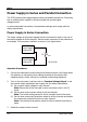
DP700 series power supply provides the trigger function, including trigger input and
trigger output. Trigger input indicates that the external trigger input signal controls
the on/off status of the channel output. Trigger output indicates that controlling the
on/off status of the channel output can enable the instrument to output the specified
signal. When multiple power supplies are in serial or parallel connection, enabling the
external trigger function can realize the synchronous output for multiple power
supplies.
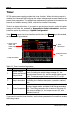
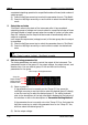
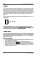
Pin 8 of the RS232 interface on the rear panel is used for trigger input, and Pin 7 for
trigger output.
Trigger is an optional function. If you want to use the trigger function, order the
option based on the Order No. available in "Appendix A: Order Information", and
then install the option by referring to "Option Configuration".
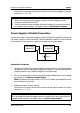
Trigger Input
Pin 8 of the RS232 interface on the rear panel is used to receive the external trigger
input signal. When it receives a high level signal (≥ 2.1 V, 10 mA), the channel output
will be turned on; when it receives a low level signal (≤0.7 V, 10 mA), the channel
output will be turned off.
Operation Procedures:
1. Turn off the instrument. Connect the external trigger input signal to Pin 8 of the
RS232 interface on the rear panel.
2. Connect the load with the channel output terminals on the front panel.
3. Turn on the instrument. Press System to enter the system utility interface. By
default, the "Setting" tab is selected. Press the Up/Down arrow key to switch the
parameter focus to "Trig In", and press the Left/Right arrow key or the knob to
enable the trigger input function.
Pin 7: TRIG_OUT
Pin 8: TRIG_IN