
User manual

Chapter 2 Front Panel Operations RIGOL
DP700 User’s Guide 2-9
At this time, the voltage of the load is the sum of the output voltages of the two
channels (V
L
= V
1
+ V
2
).
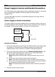
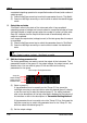
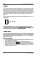
Power Supply in Parallel Connection
The output current of the power supplies that are connected in parallel is the sum of
the output currents of all the channels. Take the parallel connection of two channels
as an example. The connection method is as shown in the figure below.
Power Supply
Channel #1
-
+
Power Supply
Channel #2
-
+
I
1
I
L
R
Load
I
2
I
L
=I
1
+I
2
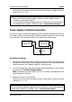
Operation Procedures:
1. Connect the load and the channel output terminals as shown in the figure above.
Pay attention to the polarity when making connections. (The channels follow the
"positive-positive" and "negative-negative" connection rule.)
2. Turn on the instrument, and then set proper output parameters for each channel
by referring to "Constant Voltage Output".
Note: All channels can work either in the CV or CC mode, which depends on the
actual situation of the load.
3. Enable the output of each channel.
At this time, the current of the load is the sum of the output currents of the two
channels (I
L
= I
1
+ I
2
).
Tip
1. When connecting the power supply in series, the total voltage in series
connection cannot exceed 240 V.
2.
You can enable the external trigger function to realize the synchronous output
for multiple power supplies. For details, refer to "Synchronous Output".
Tip
You can enable the external trigger function to realize the synchronous output for
multiple power supplies. For details, refer to "Synchronous Output".