
User manual


RIGOL
DP700 Quick Guide 7
English
A
C S
EL
E
CTO
R
10
0
Va
c 120Vac 220Vac 240Vac
100V T
5A
120V 250Vac
220
V T
2.
5A
240
V 250
Vac
F
U
SE
R
AT
IN
G
R
IGO
L TE
CHN
OLOG
IES
,IN
C.
MAD
E INC
HIN
A
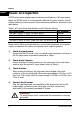
Figure 2 Rear Panel
Note: Pin 7 and Pin 8 of the RS232 interface are not used in remote communication.
They are
used in the trigger function (optional).
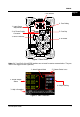
Figure 3 Main Interface
4. Output Setting
2. Actual Output
Status
5. System Status Icons
3. Help Information
1. Actual Output Mode
1. Input Power
Requirement
2. AC Power Supply
Connector
3. RS232 Interface
6. Fuse Rating
5. Fuse Cap
4. Air Outlet
7. AC Selector