
User manual
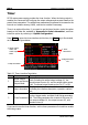
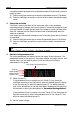
Table Of Contents
- Guaranty and Declaration
- Safety Requirement
- DP700 Series Overview
- Document Overview
- Chapter 1 Quick Start
- Chapter 2 Front Panel Operations
- Chapter 3 Remote Control
- Chapter 4 Troubleshooting
- Chapter 5 Specifications
- Chapter 6 Appendix
- Index
RIGOL Chapter 2 Front Panel Operations
2-10 DP700 User’s Guide
Timer
DP700 series power supply provides the timer function. When the timing output is
enabled, the instrument will configure the output voltages and currents based on the
preset timer parameters. The edited timer parameters are allowed to be saved to the
internal non-volatile memory (NVM), and can be recalled if necessary.
Timer is an optional function. If you want to use the timer function, order the option
based on the Order No. available in "Appendix A: Order Information", and then
install the option by referring to "Option Configuration
".
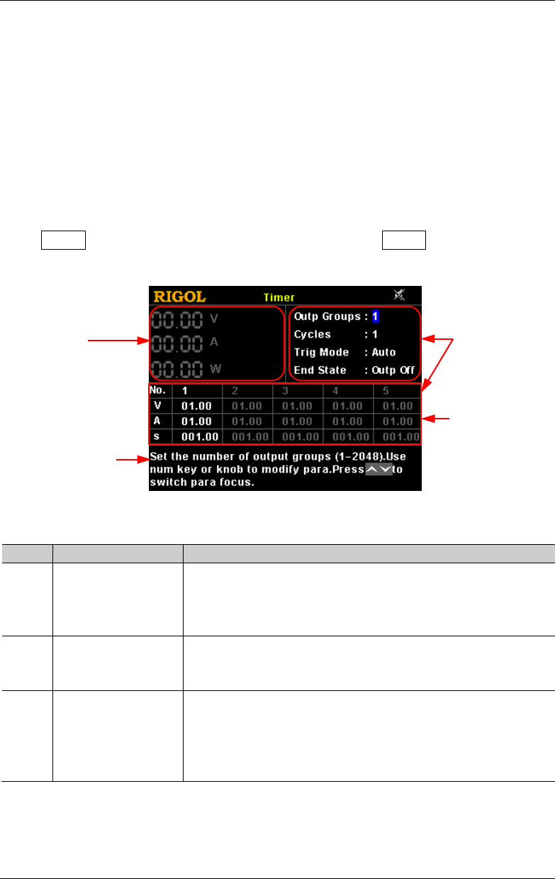
Press Timer to enter the timer interface (at this time, the Timer key is illuminated),
as shown in the figure below.
Figure 2-1 Timer Interface
Table 2-1 Timer Interface Description
No. Name Description
1
Actual Output
Status and Actual
Output Mode
Displays the actual output status of the channel in real
time, including the actual output voltage (V), the
actual output current (A), and the actual output power
(W). The actual output mode can be CV, CC, or UR.
2 Help Information
Displays the help information of the current interface,
including the interface description, operation method,
etc.
3 Timer Parameters
Includes the number of output groups, the number of
cycles, trigger mode, end state, and timing parameter
list. The timing parameter list consists of the group ID,
the output voltage (V), the output current (A), and
duration time (s).
If you want to use the timer function, set the timer parameters first and then enable
the timing output.
1. Actual Output
Status and
Actual Output
Mode
3. Timer
Parameters
Timing Parameter
List
2. Help Information