
User manual


5
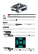
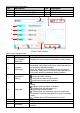
Table 2 Rear Panel Description
No.
Description
No.
Description
1
10MHz In/Out Connector
4
USB HOST
2
CH1 Sync/Ext Mod/Trig/FSK Connector
5
USB DEVICE
3
CH2 Sync/Ext Mod/Trig/FSK Connector
6
AC Power Cord Connector
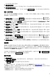
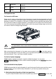
Figure 3 User Interface
Table 3 User Interface Icons
No.
Name
Description
1
Channel Output
Configuration
Status Bar
Displays the current output configuration of the channel.
2
Interface
Switchover
When left point is grayed out and the right point is
illuminated, sliding right on the touch screen can switch to
the waveform selection interface.
When the left point is illuminated and the right point is
grayed out, sliding left on the touch screen can switch to
the current waveform parameter setting interface.
3
Information
Setting
: opens the Store interface.
: opens the Utility interface.
: performs the channel copy function.
: performs the screen print operation.
4 Status Bar
: indicates that the front-panel keys and the screen are
locked.
: indicates that the beeper is disabled.
: indicates that the instrument is in
programming-controlled mode.
: indicates that the instrument has been successfully
connected to the local area network by using the network
cable.
: indicates that a USB storage device is found.
5
Waveform
Displays the currently selected waveform of each channel.
6
Interface Label
Displays the label of the current interface.
7 Frequency
Displays the frequency of the current waveform of each
channel.
7
8
9
10
1 2 3
6 5 4