
User`s manual


17
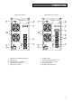
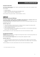
INSTALLATION AND USE
Table 2
Battery LED bar
Battery level
1 2 3 4 5
0%~20% ●
20%~40% ● ●
40%~60% ● ● ●
60%~80% ● ● ● ●
80%~100% ● ● ● ● ●
Table 3
Battery LED bar
Input Voltage
1 2 3 4 5
190V~200V ●
200V~230V ● ●
230V~250V ● ● ●
250V~260V ● ● ● ●
>260V ● ● ● ● ●
Tab. 4
Load LED bar
Load level
25 50 75 100
!
0~5%
5~25%
●
25%~50%
● ●
50%~75%
● ● ●
75%~102%
● ● ● ●
>102%
● ● ● ● ●
● LED on with steady light
♦ LED with flashing light on (1 flash per second)
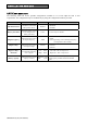
OVERLOADS ON THE UPS
The following table shows how the UPS reacts when mains and battery overloads occur and indicates the time
that the UPS will remain powered.
OVERLOAD LEVEL
LOAD POWER TIMES
(off mains)
LOAD POWER TIME
(off battery)
102% < Load ≤ 109%
Switches to bypass after 30 min
Shutdown after 30 min (if battery
back up time allows)
110% <= Load ≤ 130%
Switches to bypass after 30 sec Shutdown after 30 sec
130% < Load ≤ 150%
Switches to bypass after 10 sec Shutdown after 10 sec
Load > 150% Switches to bypass after 0.5 sec Shutdown after 0.5 sec
Short circuit Immediate shutdown Immediate shutdown