
User`s manual


0MNUOC1RUA_GB (614-06498-00)
INSTALLATION AND USE
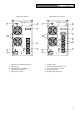
LED INDICATOR PANEL
This chapter gives a detailed description of all LED indicator panel.
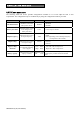
ICON STATUS DESCRIPTION
Red / Steady Indicates an fault
Red /
Flashing
The UPS is in stand-by mode
Green / Steady The UPS is operating on mains power
Green / Flashing
The UPS is operating off the bypass
The voltage input is out of the accepted range
Green / Steady
The UPS is operating in battery mode and will beep at regular
intervals.
Green / Flashing
When operating off battery power, the UPS signals that it is about to
switch off due to end of discharge. In this state, it beeps at regular
intervals of 1 sec. (see Tab. 1)
Red / Steady Indicates battery failure
Yellow / Steady The loads connected to the UPS are powered by the bypass
Represents the estimated percentage of battery charge by 5 LEDs
(see table 2)
Green / Active
Hold the ON button down for at least 10 seconds to show the input
voltage value (see table 3)
Green – Red /
Active
Indicates the % of load applied to the UPS in relation to the nominal
value. the last icon indicates overload (see table 4)
Tab. 1
Battery status LED - battery working -
Normal
●
Low
♦
● LED with steady light on
♦ LED with flashing light on (1 flash per second)