OPERATOR’S MANUAL 13 in. THICKNESS PLANER R4330 Your new planer has been engineered and manufactured to our high standards for dependability, ease of operation, and operator safety. When properly cared for, it will give you years of rugged, trouble-free performance. WARNING: To reduce the risk of injury, the user must read and understand the operator’s manual before using this product. Thank you for buying a RIDGID® product.
table of contents Introduction....................................................................................................................................................................... 2 General Safety Rules......................................................................................................................................................3-4 Specific Safety Rules...............................................................................................................
GENERAL SAFETY RULES ALWAYS WEAR SAFETY GLASSES WITH SIDE SHIELDS. Everyday eyeglasses have only impactresistant lenses, they are not safety glasses. WARNING: Read and understand all instructions. Failure to follow all instructions listed below, may result in electric shock, fire and/or serious personal injury. SECURE WORK. Use clamps or a vise to hold work when practical. It’s safer than using your hand and frees both hands to operate tool. DON’T OVERREACH.
GENERAL SAFETY RULES Inspect TOOL CORDS periodically. If damaged, have repaired by a qualified service technician at an authorized service facility. The conductor with insulation having an outer surface that is green with or without yellow stripes is the equipment-grounding conductor. If repair or replacement of the electric cord or plug is necessary, do not connect the equipment-grounding conductor to a live terminal. Repair or replace a damaged or worn cord immediately.
SPECIFIC SAFETY RULES NEVER PUT YOUR FINGERS into the dust hood or under the cutter guard. ALWAYS TURN OFF TOOL before disconnecting it to avoid accidental starting when reconnecting to power supply. ALLOW THE Cutterhead to reach full speed before using the planer. IF THE POWER SUPPLY CORD IS DAMAGED, it must be replaced only by the manufacturer or by an authorized service center to avoid risk. Replacement parts.
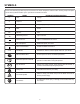
SYMBOLS Some of the following symbols may be used on this tool. Please study them and learn their meaning. Proper interpretation of these symbols will allow you to operate the tool better and safer.
SYMBOLS The following signal words and meanings are intended to explain the levels of risk associated with this product. SYMBOL SIGNAL MEANING DANGER: Indicates an imminently hazardous situation, which, if not avoided, will result in death or serious injury. WARNING: Indicates a potentially hazardous situation, which, if not avoided, could result in death or serious injury. CAUTION: Indicates a potentially hazardous situation, which, if not avoided, may result in minor or moderate injury.
ELECTRICAL Extension Cords SPEED AND WIRING Use only 3-wire extension cords that have 3-prong grounding plugs and 3-pole receptacles that accept the tool’s plug. When using a power tool at a considerable distance from the power source, use an extension cord heavy enough to carry the current that the tool will draw. An undersized extension cord will cause a drop in line voltage, resulting in a loss of power and causing the motor to overheat.
ELECTRICAL MOTOR safety protection This motor should be blown out or vacuumed frequently to prevent sawdust buildup which can interfere with normal motor ventilation. Connect this tool to a power source with the appropriate voltage for your model and a 15-amp branch circuit with a 15-amp time delay fuse or circuit breaker. Using the wrong size fuse can damage the motor. OVERLOAD PROTECTOR / RESET BUTTON If the motor won’t start, turn off the power switch immediately and unplug the tool.
glossary of terms Non-Through Cuts Any cutting operation where the blade does not extend completely through the thickness of the workpiece. Push Blocks (for jointer planers) Device used to feed the workpiece over the jointer planer cutterhead during any operation. This aid helps keep the operator's hands well away from the cutterhead. Push Blocks and Push Sticks (for table saws) Devices used to feed the workpiece through the saw blade during cutting operations.
FEATURES PRODUCT SPECIFICATIONS Feed Rate................................................................26 FPM Input...................................120 V, 60 Hz, AC Only, 15 Amp No Load Speed....................................10,000 r/min. (RPM) Max. Planing Height......................................................6 in. Max. Planing Width.....................................................13 in. Max. Planing Depth....................................................1/8 in.
FEATURES KNOW YOUR planer IND-I-CUT™ DEPTH Gauge See Figure 3. The safe use of this product requires an understanding of the information on the tool and in this operator’s manual as well as a knowledge of the project you are attempting. Before use of this product, familiarize yourself with all operating features and safety rules. REPEAT-A-CUT™ The Ind-I-Cut™ depth gauge is located on the front of your planer and measures depth of cuts up to 1/8 in.
LOOSE PARTS The following items are included with the tool: Blade / tool storage Switch key Hex key (4 mm) Magnetic blade tool Hex head screw (2) Depth adjustment handwheel Dust hood Dust hood knobs (2) Handwheel knob Operator’s manual DUST Hood knobs DUST Hood SWITCH KEY hex key HEX HEAD SCREW magnetic blade tool HEX HEAD SCREW DEPTH ADJUSTMENT HANDWHEEL HANDWHEEL KNOB BLADE / TOOL STORAGE Fig.
ASSEMBLY UNPACKING Mark holes on workbench where planer is to be mounted using holes in planer base as a template for hole pattern. This product requires assembly. Note: Every RIDGID® Thickness Planer is tested at the factory to insure its performance. You may see small amounts of wood dust and chips on your new planer. Carefully lift the tool from the carton and place it on a level work surface. NOTE: This tool is heavy.
ASSEMBLY DUST hood KNOBS installing handwheel knob See Figure 7. Locate the handwheel knob and screw from among the loose parts. Insert the screw through the hole in the handwheel and tighten screw securely. Using the hex head screw, attach the depth adjustment handwheel securely to the planer. DUST ADAPTOR slot INSTALLING THE DUST HOOD See Figure 8.
ASSEMBLY LEVELING THE TABLE EXTENSIONS See Figure 9. The infeed and outfeed table extensions are attached to the planer. Shipped in a folded, upright position, the table extensions must be in the down position before planing can begin. For accurate planing, table extensions must be level with the planer table. NOTE: For optimum performance, always check to make sure the table extensions are level before beginning planing operations.
OPERATION thickness planing WARNING: Thickness planing sizes workpiece to desired thickness while creating a smooth, level surface. Thickness of each cut will depend on type of wood (hardwood versus softwood), width of workpiece, straightness, dryness, and grain composition. Whenever working with a new type of wood, make thin test cuts on a scrap piece of wood first to determine potential problems with the workpiece. Do not allow familiarity with tools to make you careless.
OPERATION AVOIDING SNIPE POWER SWITCH Snipes, or depressions made at either end of a workpiece by cutter blades, can occur when the board is not properly supported. Although snipe may be barely noticeable, it is important to keep the workpiece parallel and flat with the planer table to minimize snipe. Butting workpieces endto-end as they are fed through the planer will minimize the problem, especially for shorter pieces, because it provides a more stable feed. For workpieces longer than 48 in.
OPERATION adjusting the planing depth See Figure 11. The depth adjustment handwheel is used to set the amount of wood being removed in a planing pass. Never make a planing cut deeper than 1/8 in. for material up to 6 in. wide or 1/16 in. for material between 6 in. and 13 in. wide. NOTE: Do not continuously use the planer at the maximum depth of cut (1/8 in.) as it will damage the motor. Rotate the depth adjustment handwheel to position the cutterhead at the desired planing depth.
OPERATION Push slightly on the board and allow the automatic feed to take the board. Release the board to allow the automatic feed to function properly. Do not push or pull on the workpiece. Move to one side at the rear of the planer and receive the planed lumber by grasping it in the same manner as it was fed. Do not grasp any portion of the board which has not gone past the outfeed area of the table. REPLANING using repeat-a-cut™ See Figure 14.
ADJUSTMENTS THICKNESS SCALE WARNING: Before performing any adjustment, make sure the tool is unplugged from the power supply and the switch is in the OFF position. Failure to heed this warning could result in serious personal injury. SCALE INDICATOR SCREWS SCALE INDICATOR THICKNESS SCALE ADJUSTMENT See Figure 15. Located on the right front of the planer, the thickness scale shows the depth of the finished workpiece.
ADJUSTMENTS repeat-a-cut™ See Figure 17. Plane a scrap piece of wood and measure the depth of the finished piece. If an adjustment is needed: Unplug the planer. Pull the replane indicator straight out to remove. Using the hex key provided, remove the hex head screw from the depth adjustment handwheel. Remove the handwheel. Remove the screws on the top and right side panel of the planer. Carefully lift and pull the side panel cover off.
MAINTENANCE CLEANING WARNING: Sawdust buildup and other debris can cause the tool to plane inaccurately. Periodic cleaning and waxing is needed for accurate, precision planing. Do not allow sawdust to accumulate on the planer. Clean the dust hood after each use. When servicing, use only identical replacement parts. Use of any other part may create a hazard or cause product damage.
MAINTENANCE Cord storage See Figure 19. For convenience, your planer comes equipped with cord storage. When not in use, the power cord should be wrapped around the planer. CAUTION: Check extension cords before each use. If damaged, replace immediately. Never use tool with a damaged cord since touching the damaged area could cause electrical shock resulting in serious injury. BRUSH REPLACEMENT See Figure 20.
MAINTENANCE BLADE REPLACEMENT Cutterhead LOCK See Figures 21 - 23. The planer is equipped with replaceable/disposable doubleedged cutter blades attached to a rotating cutterhead. Worn cutter blades will affect cutting accuracy and may produce ridges on the workpiece. Unplug the planer. Lower the cutterhead assembly. From the back of the planer, remove the two dust hood knobs holding the dust hood in place. Remove the dust hood. NOTE: The cutterhead lock will engage when the head is rotated.
troubleshooting Problem Snipe (depressions at ends of workpiece) Possible Cause Dull cutter blades Incorrect butted stock Solution Unit not securely mounted Replace or turn cutter blades. Butt pieces end-to-end as they are fed into planer. Tighten lag bolts. Torn grain Too deep a blade setting Workpiece being fed against grain Dull cutter blades Reduce depth of cut. Feed other end of board first. Replace or turn cutter blades.
WARRANTY RIDGID® HAND HELD AND STATIONARY POWER TOOL 3 YEAR LIMITED SERVICE WARRANTY WHAT IS NOT COVERED Proof of purchase must be presented when requesting warranty service. Limited to RIDGID® hand held and stationary power tools purchased 2/1/04 and after. This product is manufactured by One World Technologies, Inc. The trademark is licensed from RIDGID®, Inc. All warranty communications should be directed to One World Technologies, Inc.
OPERATOR’S MANUAL 13 in. THICKNESS PLANER R4330 Customer Service Information For parts or service, contact your nearest RIDGID authorized service center. Be sure to provide all relevant information when you call or visit. For the location of the authorized service center nearest you, please call 1-866-539-1710 or visit us online at www.ridgid.com. The model number of this tool is found on a plate attached to the motor housing. Please record the serial number in the space provided below.