® INNOVATION IN MOBILITY ™ RDO2900 Series Internal Power Swing Door Operator PRINT Service Manual 02/14/02 32DDO06.A U.S.
This Ricon service manual is for use by qualified service technicians, and is not intended for use by nonprofessionals (do-it-yourselfers). The manual provides essential instructions and reference information, which supports qualified technicians in the correct installation and maintenance of Ricon products. Qualified service technicians have the training and knowledge to perform maintenance work properly and safely.
REVISION RECORD REV PAGES DESCRIPTION OF CHANGE ECR/ECO 32DDO06. A All New release, in two-book format. 3882/4864 END OF LIST ii 32DDO06.
TABLE OF CONTENTS Chapter: I. INTRODUCTION............................................................................................................................. 1-1 A. B. C. D. II. Page RICON ONE-YEAR LIMITED WARRANTY .................................................................................................... 1-1 SHIPMENT INFORMATION ............................................................................................................................
This page intentionally left blank. iv 32DDO06.
I. INTRODUCTION T he RICON RDO2900 Series Internal Power Swing Door Operator electrically opens and closes swing-type van doors. They have been designed to operate in most full size vans, and provide up to 90° of motion for each door. The power door operators are installed within the doors behind the door panel. Adjustable bell-cranks provide smooth operation, and a splined connection between the crank-arm and the motor output shafts maintain wobble-free operation.
RICON CORPORATION ONE-YEAR LIMITED WARRANTY Ricon Corporation (Ricon) warrants to original purchaser of this product that Ricon will repair or replace, at its option, any part that fails due to defective material or workmanship as follows: • Repair or replace parts for a period of one year from date of purchase. A complete list of parts covered by this warranty can be obtained from a Ricon authorized dealer. If You Need to Return a Product: Return this Ricon product to your installing dealer.
B. SHIPMENT INFORMATION Ricon does not sell directly to the user because of the specialized nature of this product. Instead, the product is distributed through a worldwide network of authorized Ricon dealers who perform the actual sale and installation. • • C. When the product is received, unpack the product and check for freight damage. Claims for any damage should be made to the carrier immediately. Be sure the installation kit contains all items listed on the kit packing list.
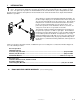
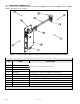
D. COMPONENT TERMINOLOGY The references used throughout this manual are illustrated in Figure 1-1 and defined in Table 1-1. Refer to Chapter IV, “Spare Parts” for more details. FIGURE 1-1: RD02900 SERIES INTERNAL POWER DOOR OPERATOR (RIGHT DOOR MODEL SHOWN) TABLE 1-1: RDO2900 SERIES COMPONENT TERMINOLOGY REF NAME DESCRIPTION 1 Right 2 Left 3 Front 4 Rear 5 Main plate Mounts the door operator assembly to the vehicle door.
II. INSTALLATION T he chapter provides instructions for installing the RICON RDO2900 Series Internal Power Swing Door Operator into full-size 1992 and later Ford vans, 1990 and later Chevrolet & GMC vans, and 1994 and later Dodge vans. Custom installations are also possible in other types of vehicles. If a question arises that is not covered in this manual, or by the Installation Instructions provided with this product, contact Ricon Product Support for assistance.
A. MECHANICAL INSTALLATION To install the power door operators, refer to the following sections and perform the procedures carefully and in the order that they are presented. Be certain that the installation instructions are followed exactly and do not eliminate any steps or modify the product. 1. VEHICLE PREPARATION Prepare the vehicle for installation: a. Safely park vehicle on a flat, level surface and turn engine off. WARNING! § § § b. c. d. e. f. g. h. 2.
3. REAR-DOOR INSTALLATIONS a. Attach angle bracket to the clevis bracket. b. Refer to the kit installation instructions. Position and level angle/clevis bracket. Mark the bracket holes to be drilled. c. Using a 3/16" diameter drill bit, carefully drill holes into door post. d. Refer to Figure 2-2. (Figure also applies to left-rear door installation except viewed in the opposite direction. Bracket appearance may vary slightly for different vehicle manufacturers.
j. Refer to the kit installation instructions and Figure 2-3 or Figure 2-4, as applicable. Position and fasten the top bracket to the door. Be sure to insert bolt so that the hex-nut is installed behind the door panel. FIGURE 2-3: LEFT-REAR DOOR OPERATOR MOUNTING LOCATIONS FIGURE 2-4: RIGHT-REAR DOOR OPERATOR MOUNTING LOCATIONS k. Refer to the kit installation instructions. Locate bottom bracket down and behind lower door panel, and fasten bracket to the pane.
B. ELECTRICAL INSTALLATION 1. Refer to the kit installation instructions. Drill a 3/4" diameter hole in the door frame. CAUTION! Check vehicle before drilling. Do not drill into factory wiring, hydraulic lines, fuel lines, fuel tank, etc. 2. Drill a 3/4" diameter hole in the door jamb opposite the hole drilled in the door frame. 3. Deburr all drilled holes, installed the supplied grommet, and route the main harness assembly through the grommet and into the vehicle. 4.
C. FINAL ADJUSTMENTS The power door operators are shipped with the actuator arms in the "Open" position. To make certain that the vehicle doors are opened and closed properly, it may be necessary to adjust the actuator rod length and limit switches. If more than one power door operator is installed in the same vehicle, adjust the operators one at a time and repeat the procedure for the other operator. To adjust the power door operators, follow this procedure: 1.
8. Refer to Figure 2-7. Adjust the length of the hex-rod assembly as required until the left door closes tightly. To adjust, loosen locknuts at ends of hex-rod, rotate the hex-rod, and then retighten the locknuts. FIGURE 2-7: HEX ROD ADJUSTMENT 9. Remove actuator arms from the operators. Leave hex-rod assemblies attached at clevis bracket assemblies. D. INSTALLATION COMPLETION 1. 2. 3. 4. 5. 6. If power door operators are installed in side doors, reinstall stepwell cover.
E. CUSTOMER ORIENTATION IMPORTANT - Customer Orientation Ricon Sales/Service Personnel must review the Warranty and Operator Manual with the customer to be certain they understand safe operation of the equipment. Instruct the customer to follow the operating instructions without exception. - Refer to Figure 2-8 and verify that all decals are properly located and affixed as shown. FIGURE 2-8: DECAL LOCATIONS AND PART NUMBERS 2-8 32DDO06.
III. MAINTENANCE R egular maintenance of the RICON RDO2900 Series Internal Power Swing Door Operator is required to provide optimum performance. During the Ricon warranty period, maintenance inspections must be performed by an authorized Ricon service technician at least once every six months, or sooner depending on usage. After the warranty period, maintenance inspections are recommended at the same time intervals. WARNING! THIS RICON PRODUCT IS HIGHLY SPECIALIZED.
B. TROUBLESHOOTING GUIDE The troubleshooting guide is designed to provide a logical starting point to locate general problems that could occur with the power door operators. However, not all possible problems or combinations of problems are listed. For troubleshooting the door operators, refer to Table 3-2. The guide does not incorporate routine safety precautions or preliminary procedures and assumes that the vehicle battery is fully charged and the battery terminals/connectors are clean and tight.
CLOSE MOTION Only left door closes Right motor defective. Replace. Ground connection. DOOR OPERATOR SEQUENCE Clean/repair. Sequence is correct, Actuator arm is installed upsidebut open is closed down. Motor wires reversed. Reverse actuator arm. Motors are shipped with brown wire toward inside of vehicle. END OF TABLE C. ELECTRICAL WIRING DIAGRAM 1. DIAGRAM LEGEND a.
c. Wiring Diagram Labels d. Electrical Symbols FIGURE 3-2: DIAGRAM SYMBOLS 3-4 32DDO06.
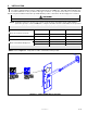
2. DOOR OPERATOR LIMIT SWITCH STATE Refer to Figure 3-3. The limit switch actuation diagram shows the state of all limit switches as the doors go from fully closed to fully open. The solid (? ) line indicates the normally closed circuit is active, while the two thin lines ( ) indicate the normally open circuit is active. The dotted lines (????) are used to show the switch states beyond the normal travel boundaries of the door.
FIGURE 3-4: RD02900 ELECTRICAL WIRING DIAGRAM 3-6 32DDO06.
IV. SPARE PARTS T his chapter contains parts diagrams and lists for the RICON RDO2900 Series Internal Power Swing Door Operator. The parts diagram is an exploded view of the operator, with components referenced by numbers. The accompanying parts list has the part reference number, description, quantity used, and the Ricon stock number. To order a part, locate the part on the drawing and note the reference number.
FIGURE 4-1: RD02900 SERIES POWER DOOR OPERATOR (LEFT AND RIGHT) 4-2 32DDO06.
FIGURE 4-1: POWER DOOR OPERATOR RDO2900 SERIES SERIAL No's. 290001 – PRESENT REF DESCRIPTION QTY PART NO.
This page intentionally left blank. 4-4 32DDO06.