
Owner manual


Series NKL, NKLP, NKS, NKSP, NK, NKP Page 6
9520-070-en Revision 04
TM 7113 Edition 05/2008
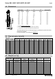
1.4 Dimensions
Nom. size[
E
1
T
1
L
2
Connection
3
[mm] [inch] [mm] [mm] [mm]
50 2“ 28 4 43 F07
80 3“ 67 17,5 46 F07
100 4“ 87 24,5 52 F07
150 6“ 142 48 56 F10
200 8“ 193 71 60 F10
250 10“ 243 92 68 F12
300 12“ 292 112 78 F12
350 14“ 343 137 78 F14
400 16“ 389 150 102 F14
1 See also Section 6.4, paragraph 1
2 Face to face to DIN EN 558-1, series 20 (ISO 5752, series 20)
3 Connections for worm gears and brackets as per DIN ISO 5211
The inside diameter of the mounted pipe flanges must always be greater than the di-
mension E in the table!
For more dimensions, see drawings in Section 10.
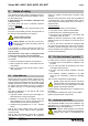
1.5 Flow rate value kv [m³/h]
Angel of opening
Nom. Size
[mm] [inch]
20° 30° 40° 50° 60° 70° 80° 90°
50 2“ 1 6 13 24 41 67 104 120
80 3“ 5 22 47 82 126 197 264 282
100 4“ 11 27 52 93 155 247 412 456
150 6“ 37 84 164 276 431 702 1126 1254
200 8“ 62 170 354 532 912 1371 2212 2503
250 10“ 85 285 512 882 1451 2256 3692 4083
300 12“ 159 421 835 1378 2282 3633 5735 6512
350 14“ 230 610 1210 2000 3300 5270 8320 9450
400 16“ 295 780 1550 2560 4240 6750 10650 12100
1.6 Weights (ca. kg)
Nom. size Lug style body
Sandwich-
body
Double-flange
body
[mm] [inch]
open
staff ende
open
staff ende
open
staff ende
Lever Gear
50 2“ 4,5 3,5 4,0 0,7 4,0
80 3“ 7,5 4,5 5,0 0,7 4,0
100 4“ 9,5 6,0 7,0 0,7 4,0
150 6“ 16,0 11,0 12,0 3,7 4,5
200 8“ 23,0 15,0 19,5 3,7 4,5
250 10“ 35,0 25,0 29,0 -- 9,5
300 12“ 54,0 33,0 47,5 -- 9,5
350 14“ 68,0 47,0 -- -- 15,0