INSTALLATION AND OPERATING MANUAL Series GUT/F Overflow and pressure relief valve DN 25 spring-loaded Keep for future use! This operating manual must be strictly observed before transport, installation, operation and maintenance Subject to change without notice. Reproduction is generally permitted with indication of the source.
Series GUT/F Page List of Contents List of Contents ......................................... 2 Relevant documents ................................. 2 1 Technical data ...................................... 3 1.1 Type plate, CE and body markings, type plate test pressure ....................................... 3 1.2 Tightening torques ....................................... 4 1.3 Screw-in tool for valve seat ......................... 4 1.4 Pressure-temperature diagram.................... 4 2 Safety .....
Series GUT/F 1 Page 3 Technical data Manufacturer : Installation position : Richter Chemie-Technik GmbH Otto-Schott-Str. 2 D-47906 Kempen Telephone: +49 (0) 2152 146-0 Fax: +49 (0) 2152 146-190 E-Mail: richter-info@richter-ct.com Internet: http://www.richter-ct.com A direction arrow on the shell indicates the direction of flow. See Section 6.5. Dimensions and individual parts : Please pay attention to the drawing in Section 10. 1.
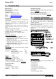
Series GUT/F 1.2 Page 4 Tightening torques 1.3 All screws greased, tighten in diametrically opposite sequence! The tightening torques for pipe screws and body screws mentioned must not be exceeded. For an exception, see Section 8, Flange connection valve / pipe is leaking. The following tightening torques are recommended. Pipe screws, flanges to ISO/DIN Flange nom.
Series GUT/F 2 Page 5 Safety This operating manual contains fundamental information which is to be observed during installation, operation and maintenance. It must be read before installation and commissioning! For overflow valves which are used in potentially explosive areas, see Section 3. Installation and operation are to be performed by qualified staff. The area of responsibility, authority and supervision of the staff must be regulated by the customer.
Series GUT/F 3 Page 6 Safety notes for applications in potentially explosive areas based on the Directive 94/9/ EC (ATEX) The valves are intended for use in a potentially explosive area and are therefore subject to the conformity assessment procedure of the directive 94/9/EC (ATEX).
Series GUT/F 4 Safety note for valves, certified to Clean Air Act (TA-Luft) On request, this valve can be supplied compliant with the German Clean Air Code. Certificate / Manufacturer Declaration Validity is dependent on the operating instructions being read and observed. 5 Page 7 In particular, servicing must be conducted at regular intervals, and the bolted connections relevant for tightness must be inspected and retightened if necessary.
Series GUT/F 6 Page 8 Installation The installation conditions to the AD 2000 Code A2 (on pressure vessels) and TRD721 are to be observed. They are major preconditions for the safe operation of the valve. Examine valve for in-transit damage and do not install any damaged overflow valves. Before installation the valve and the connecting pipe must be carefully cleaned to remove any dirt, especially hard foreign matter.
Series GUT/F Page 9 6.2.3 Discharge conditions and reaction forces At low temperatures: Outlet lines must be protected against freezing. This applies in particular if gas cooling as a result of expansion is to be expected or lines are laid outdoors. With crystallising media: In the case of media which tend to crystallise, solidify or stick, appropriate action must be taken to ensure that the solidification process cannot take place in the inlet or outlet lines or in the body (e.g.
Series GUT/F 7 Operation 7.1 Initial commissioning Normally, the valves have been tested for leaks with water. Unless otherwise agreed there could be residual amounts of water in the flow section of the valve; this could result in a possible reaction with the operating medium. To prevent leaks, all connection screws should be retightened after the initial loading of the valve with operating pressure and operating temperature. See Section 9.3. 7.2 7.
Series GUT/F 8 Page 11 Malfunctions Overflow valve is leaking Is there foreign matter between the seat and plug? Is there any wear or damage to the seat or plug? Actuation of the lifting lever can help to regain the required sealing effect. If this does not succeed in stopping the leak, the sealing surface of the plug must either be reworked or the plug or seat must be replaced. The lift given in the test certificate is not achieved Are the bellows impeded in their movement by external influences (e.g.
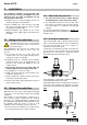
Series GUT/F 9.4 Page 12 Adjustment of the test pressure 9.6.1 Dismantling of the plug and seat Unscrew cap 207. Undo groove nut 509/1. Adjust the spring tension with the straining screw 581 to the specified test pressure. Counter straining screw 581 with the groove nut 509/1 Check test pressure. Screw on cap 207 and tighten. Have valve lead-sealed. The data specified in the test certificates are to be observed. 9.
Series GUT/F 9.7 Tests Following the assembly of the valve, the stroke and the test pressure must be checked. 9.7.1 Stroke Lift check: The measurement can be made with a slide calliper gauge and a depth indicator to DIN 862. The lift is derived from the difference in the two heights. It must be at least as high as the lift given in the test certificate. Page 13 9.7.2 Test pressure This test should take place on a test bench with a neutral medium such water.
Series GUT/F 10.
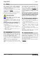
Series GUT/F Page 15 10.4 Dimensional drawing EN 558 series 1 Nominal size D0 H H1 ANSI/ISA-75.08.01 Class 150 L ANSI/ISA-75.08.01 Class 300 L L mm inch mm inch mm inch mm inch mm mm inch mm inch 25 1“ 12 0.47 290 11.42 110 4.33 160 184 7.25 197 7.75 Flange connecting dimensions: Flanges acc. to DIN EN 1092-2, type B (ISO 7005-2, type B) PN 16 or flanges drilled to ASME 5, Class 150 Flanges acc. to ASME B16.
Richter Chemie-Technik GmbH Otto-Schott-Straße 2 D-47906 Kempen www.richter-ct.com A Unit of IDEX Corporation Konformitätserklärung nach EN ISO//IEC 17050 Declaration of Conformity according to EN ISO//IEC 17050 Produkt Product Überstromventile und Druckhalteventile Overflow and pressure relief valve Baureihe Serie GU, GUT Nennweite Size GUT - DN 25, 1“, GUT - DN 25, 1“, Seriennummer Series number ab/from 29.12.
Safety Information / Declaration of No Objection Concerning the Contamination of Richter-Pumps, -Valves and Components 1 SCOPE AND PURPOSE Each entrepreneur (operator) carries the responsibility for the health and safety of his employees. This extends also to the personnel, who implements repairs with the operator or with the contractor. Enclosed declaration is for the information of the contractor concerning the possible contamination of the pumps, valves and component sent in for repair.
Declaration about the Contamination of Richter Pumps, -Valves and Components The repair and/or maintenance of pumps, valves and components can only be implemented if a completely filled out declaration is available. If this is not the case, delay of the work will occur. If this declaration is not attached to the devices, which have to be repaired, the transmission can be rejected. Every aggregate has to have it’s own declaration.
FAX Fax No. () Pages (incl. cover sheet) () To: () Contact person: () Your order No.: Our Kom. No.: Reference: () () () Extension: - () E-Mail Address: () Date: () Serial No.: () Dear Sirs, The compliance with laws for the industrial safety obligates all commercial enterprises to protect their employees and/or humans and environment against harmful effects while handling dangerous materials.