
User guide

Series GR/F Page 4
9550-075-en Revision 01
TM 6897 Edition 10/2007
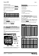
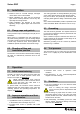
Cover screws
Flange nom.
size
Screws Tightening torque
[mm] [inch] [ISO/DIN] [Nm] [in-lbs]
15 ½“ 4 x M10 30 266
20 ¾“ 4 x M10 30 266
25 1 4 x M12 50 442
40 1½ 4 x M12 50 442
50 2 4 x M12 50 442
65 -- 4 x M12 50 442
80 3 8 x M12 50 442
100 4 8 x M12 50 442
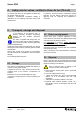
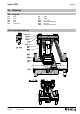
1.3 Screw-in tool for seat
Nom. diameter
[mm] [inch]
Article No.
15, 20 ½“, ¾“ 9568-96-1011
25 1“ 9568-96-1001
40 1½“ 9568-96-1002
50, 65 2“ 9568-96-1003
80 3“ 9568-96-1004
100 4“ 9568-96-1005
Fig. 1
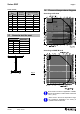
1.4 Pressure/temperature diagram
According to AD 2000
According to ASME B 16.42
When used in the area of application of ASME,
the low temperature of ASTM A395 is limited to
-20°F (-29°C).
When used in the minus temperature range,
the regulations applicable in the country in
question must be observed.