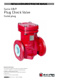
INSTALLATION AND OPERATING MANUAL Serie GR/F Plug Check Valve Solid plug Keep for future use! This operating manual must be strictly observed before transport, installation, operation and maintenance Subject to change without notice. Reproduction is generally permitted with indication of the source.
Series GR/F Page 2 List of Contents List of Contents ........................................ 2 Relevant documents................................. 2 1 Technical data...................................... 2 1.1 1.2 1.3 1.4 Name plate, CE and body markings............ 3 Tightening torques....................................... 3 Screw-in tool for seat................................... 4 Pressure/temperature diagram ................... 4 2 Notes on safety .................................... 5 2.
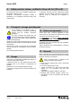
Series GR/F Page 3 Temperature range : See pressure-temperature diagram in Section 1.4. Operating pressure: from vacuum to max. 16 bar Body identification: The following are visible on the body according to DIN EN 19 and AD 2000 A4: Nominal size See pressure-temperature diagram in Section 1.4. Rated pressure Sizes : Body material DN 15, 20, 25, 40, 50, 65, 80, 100 ASME ½“, ¾“, 1“, 1½“, 2“, 3“, 4“ Manufacturer's identification Weight: Cast date Nom. size ASME ca.
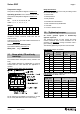
Series GR/F Page 4 Cover screws 1.4 Flange nom. size Screws [mm] [inch] [ISO/DIN] [Nm] [in-lbs] 15 20 25 40 50 65 80 100 ½“ ¾“ 1 1½ 2 -3 4 4 x M10 4 x M10 4 x M12 4 x M12 4 x M12 4 x M12 8 x M12 8 x M12 30 30 50 50 50 50 50 50 266 266 442 442 442 442 442 442 1.3 Tightening torque Pressure/temperature diagram According to AD 2000 Screw-in tool for seat Nom. diameter [mm] [inch] 15, 20 25 40 50, 65 80 100 ½“, ¾“ 1“ 1½“ 2“ 3“ 4“ Article No.
Series GR/F 2 Page 5 Notes on safety This operating manual contains fundamental information which is to be observed during installation, operation and maintenance. It must therefore be read before installation and commissioning. For valves which are used in potentially explosive areas, see Section 3. Installation and operation are to be performed by qualified staff. The area of responsibility, authority and supervision of the staff must be regulated by the customer.
Series GR/F 3 Page 6 Safety notes for applications in potentially explosive areas based on the Directive 94/9/ EC (ATEX 95) The valves are intended for use in a potentially explosive area and are therefore subject to the conformity assessment procedure of the directive 94/9/EC (ATEX).
Series GR/F 4 Safety note for valves, certified to Clean Air Act (TA Luft) On request, this valve can be supplied compliant with the German Clean Air Code. Certificate / Manufacturer Declaration Validity is dependent on the operating instructions being read and observed. 5 Storage If the valve is not installed immediately after delivery, it must be put into proper storage. It should be stored in a dry, vibration-free and wellventilated room at as constant a temperature as possible.
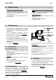
Series GR/F 6 Page 8 Installation Examine valve for in-transit damage, damaged ckeck valves must not be installed. Before installation the valve and the connecting pipe must be carefully cleaned to remove any dirt, especially hard foreign matter. During installation, pay attention to the correct tightening torque, aligned pipes and tension-free assembly. The closing operation is already initiated by the gravity of the closing element when the flow rate decreases.
Series GR/F 8 Page 9 Malfunctions Flange connection valve/pipe is leaking Retighten the flange screws to a tightening torque according to Section 1.2. If this does not remedy the leak, the recommended torques may be exceeded by 10%. If this also fails to stop the leak, dismantle and inspect the valve. 9 Flange connection main body/body end piece is leaking Retighten body screws. See paragraph "Flange connection ball valve/pipe is leaking".
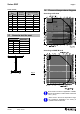
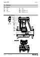
Series GR/F 10 Page 10 Drawing 10.1 Legend 100 106 204 205 522 body cover plug seat round cord 10.2 Sectional drawing 9550-075-en TM 6897 Revision 01 Edition 10/2007 801 808 901/1 902/1 920/1 936/1 guide shank hex. screw stud screw (DN 100) hex.
Series GR/F Page 11 10.3 Dimensional drawing Face to face with flanges to ISO/DIN, PN 16 or flanges drilled to ASME B16.5 Class 150 DN 15/20 25 40 50 65 80 100 L 130 160 200 230 290 310 350 H 112 156 197 205 205 313 327 dimensions in mm Face to face to ANSI/ISA 78.08.01, class 150, flanges to ASME B16.5 Class 150 * DN ½" / ¾" 1" 1½" 2" 2½" 3" 4" L 130 * 185 222 254 -- 298 350 * H 112 156 197 205 --- 313 327 dimensions in mm dimensions not acc.
Safety Information / Declaration of No Objection Concerning the Contamination of Richter-Pumps, -Valves and Components 1 SCOPE AND PURPOSE Each entrepreneur (operator) carries the responsibility for the health and safety of his employees. This extends also to the personnel, who implements repairs with the operator or with the contractor. Enclosed declaration is for the information of the contractor concerning the possible contamination of the pumps, valves and component sent in for repair.
Declaration about the Contamination of Richter Pumps, -Valves and Components The repair and/or maintenance of pumps, valves and components can only be implemented if a completely filled out declaration is available. If this is not the case, delay of the work will occur. If this declaration is not attached to the devices, which have to be repaired, the transmission can be rejected. Every aggregate has to have it’s own declaration.
FAX Fax No. () Pages (incl. cover sheet) () To: () Contact person: () Your order No.: Our Kom. No.: Reference: () () () Extension: - () E-Mail Address: () Date: () Serial No.: () Dear Sirs, The compliance with laws for the industrial safety obligates all commercial enterprises to protect their employees and/or humans and environment against harmful effects while handling dangerous materials.