
User manual


P-08 (P-10)
7 6 5 4 3 2 1 0
P-09 (P-11)
7 6 5 4 3 2 1 0
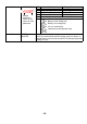
Example:
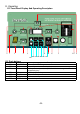
In the factory we program this output (AUX1, AUX2) to be active when one these
situations are detected:
bit Decimal value
˙Over Temperature
4 (16)
˙Over Load
5 (32) 16+32+64+128=240
˙Battery over/under voltage
6 (64)
˙Inverter is turned off or write a fault
“RUN/STOP” LED RED lit
7
(128)
The P-09 (or P-11) in the
Factory setting is 240.
-16-
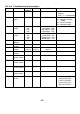
bit
bit
128
64
32
16
8
1
2
4
(
Decimal value
)
x
Batter
y
status 25%
Battery status 50%
Batter
y
status 100%
In Equalize cycle
Solar Charger action
Charger action
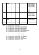
bit
bit
128
64
32
16
8
1
2
4
(Decimal value)
AC IN action.
Bypass action.
AC OUT action.
INVERTER action.
Over temperature.
Over Load.
Battery Low/High.
INVERTER is turned
off