
User manual
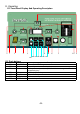


D.3.5 Connect the Solar modules: SOLAR IN +/-
Solar modules are connected on these terminals. Under no circumstances should
any other energy source i.e. wind generator be connected to these terminals.
Depending on the power of the modules, the cable cross section should be 2.5 up
to 6mm². Before connecting it is necessary to check with a Voltmeter that the
voltage of the Module meets the following values:
Invertek DAI -1500C -12xx / DAI - 3000C -12xx 17-25V / 30A
Invertek DAI -1500C -24xx / DAI - 3000C - 24xx 34-45V / 30A.
D.3.6 Connection to Aux1 & AUX2:
On these three terminals is a potential free change-over contact capable of
switching a maximum current and voltage of 16A/250V ac. The “ multi-display “
on the front of invertek can be shows the status of these contacts.
D.3.7 Connection to Remote control unit ( optional ):
The Remote control unit Invertek RCC-A is connected in the “Remote control” of
front panel with a RJ11 / 6 connector. The Remote Control can be plugged IN at
any time. Push in the connector, without forcing it, until you hear the ”click:, now the
connector is locked in place. The same applies to the plug at the Remote control
unit. The length of the cable for the Remote control should not exceed 15m, is
comes standard with 3m cable.
D.3.8 Connection to Temperature Sensor (Optional):
The Temperature Sensor Invertek-BTS-A is connected to the terminal
marked ”BTS”. The Temperature Sensor can be connect IN at any time. The
Temperature Sensor should be glued or taped to the wall of the battery or near it.
The Temperature Sensor cable must not be tied together with the battery cables
or laid in a cable bundle.
Caution: With a wrong battery voltage the Invertek can be destroyed.
-10-