
Specifications


17
2-3 Adjustability of Load Control
When setting in the load control mode, DIP Switch 7 should be placed at OFF. The LVD
(low voltage disconnect) and LVR (low voltage reconnect) are important setpoints to
protect the system battery from deep discharges that could damage the battery.
The Procedure of LVD/LVR Selection
Step 1: Press MANUAL EQU/LVR push button and LIGHT TEST push button at the
same time until the CHARGE LED turns red and LOAD LED turns green in
turns.
Step 2: Press LIGHT TEST push button at one time and observe the CHARGE LED
color and LOAD LED color changing in the following order to select the LVD
and LVR level.
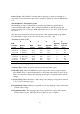
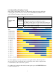
CHARGE LED LOAD LED LVR LVD
Voltage System 12V 24V 48V 12V 24V 48V
Red Red 12.6 25.2 50.4 11.1 22.2 44.4
Red Green 12.8 25.6 51.2 11.3 22.6 45.2
Green Red 13.0 26.0 52.0 11.5 23.0 46.0
Green Green 13.2 26.4 52.8 11.7 23.4 46.8
Green Orange 13.4 26.8 53.6 11.9 23.8 47.6
Orange Green 13.6 27.2 54.4 12.1 24.2 48.4
Orange Orange 13.8 27.6 55.2 12.3 24.6 49.2
Orange Red 12.0 24.0 48.0 10.5 21.0 42.0
Step 3: Press MANUAL EQU/LVR to finish the LVD/LVR level setting procedure.
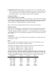
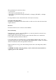
Inductive Loads (Motors)
For dc motors and other inductive loads, it is strongly recommended to install a diode
near the controller. Inductive loads can generate large voltage spikes that might damage
the controller’s lightning protection devices.
The diode should be installed near the controller, and in the orientation shown in the
diagram below:
PV+/LOAD+
DC Motor
Diode Protection