Operator’s Manual
Copyright Information CG Triumvirate is a trademark of Agfa Corporation. CG Times based upon Times New Roman under license from the Monotype Corporation. Windows is a registered trademark of the Microsoft Corporation. All other brand and product names are trademarks, service marks, registered trademarks, or registered service marks of their respective companies.
Important Safety Instructions This printer has been carefully designed to provide many years of safe, reliable performance. As with all types of electrical equipment, however, there are a few basic precautions you should take to avoid hurting yourself or damaging the equipment: • • • • • • • • • Carefully read the provided installation and operating instructions. Read and follow all warning instruction labels on the printer. Place the printer on a flat, firm, solid surface.
Contents 1 Getting Started 1.1 1.2 2 Introduction ........................................................................... 1 Unpacking.............................................................................. 1 Printer Setup 2.1 2.2 2.3 2.4 2.5 2.6 3 Printer Connections ................................................................. 2.1.1 Power Connection ........................................................ 2.1.2 Interface Connection ....................................................
5 Maintenance and Adjustments 5.1 5.2 5.3 5.4 5.5 5.6 5.7 Cleaning Intervals ................................................................... Cleaning the Printhead ............................................................. Media Width Adjustment .......................................................... Printhead Pressure Adjustment ................................................. Printhead Replacement ............................................................ Resetting the Printer.............
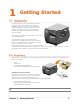
1 Getting Started 1 1..1 1 IIn nttrro od du uccttiio on n Congratulations on your I-Class Mark II printer purchase. The I-Class Mark II printer family, hereafter referred to as ‘the printer’, blends the rugged durability of die-cast construction with state-of-the-art electronics and user-friendly features to redefine the standard in industrial thermal printers. This manual provides all the information necessary to operate the printer.
Chapter 1 – Getting Started 2
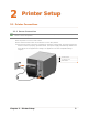
2 Printer Setup 2 2..1 1 P Prriin ntte err C Co on nn ne eccttiio on nss 2.1.1 Power Connection Before connecting the AC Power Cord or interface cables to the printer, ensure the Power On/Off Switch is in the ‘Off’ position. Place the printer on a firm, level surface. Ensure that the Power Switch on the Printer is in the ‘Off’ position. Connect the AC Power Cord to the receptacle on the back of the Printer, and then plug the AC Power Cord into a properly grounded outlet.
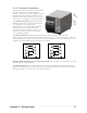
2.1.2 Interface Connection The printer can be connected to the host via the parallel, USB, serial, or optional network interface. The printer will automatically connect to the first port that delivers valid data. Once established, the printer’s power must be cycled ‘Off’ and ‘On’ to change an interface connection.
2.1.3 USB Connection USB connection to PC requires installation of drivers for both the Port and the Windows Driver itself. All the files necessary for installation are located on the Accessories CD-Rom. Connect the printer to the host PC via a standard USB Cable and follow the steps below. The following steps are for a typical Windows XP system, other versions of Windows may vary. Step A: Windows Port Driver Installation: 1. Turn on the printer and wait until the “Ready” screen appears.
8. When prompted click “Continue Anyway” 9. Windows will now load the drivers to assign the necessary ports to the printer. 10. Click Finish to close the wizard. Proceed to Step B to begin the installation of the Windows Printer Driver.
Step B: Windows Printer Driver Installation: 1. The PC will launch the “Found New Hardware Wizard” again. 2. Select the “No, not this time” radio button and then click Next. 3. Select the “Install from a list or specific (Advanced)” radio button and then click Next. 4. Select the “Search for the best driver in these locations” radio button. 5. Check the “Include this location in the search” checkbox and then click Browse. 6.
8. Select the driver that matches your model printer. (there may be multiple models listed) and then click Next. 9. When prompted click “Continue Anyway” 10. Windows will now install the necessary files for the Windows printer driver. 11. Click Finish to close the wizard. The printer can now be selected for use in the printer dialogue box of any windows application.
2 2..2 2 LLo oa ad diin ng gM Me ed diia a Load media into the printer as follows: 1. Open the media cover. Rotate and unlock the Printhead Latch and raise the Printhead Assembly. 2. Rotate the Media Guide down. Printhead Latch Printhead Assembly Media Guide 3. Slide the Roll Media onto the Media Hub. 4. Route the Media through the printer as shown. Raise the Media Guide. The Media Guide should be pushed inward so that it is just touching the edge of the Media.
5. Close the Printhead Assembly and rotate the Printhead Latch to the locked position. 6. Close the cover and press the FEED button several times to position the media and ensure proper tracking. Printhead Assembly Printhead Latch If the printer does not correctly sense the top of each label, it may be necessary to calibrate the printer (see Section 3.4 Media Calibration). The printer is factory set to use 4-inch media (and ribbon, if thermal transfer equipped).
2 2..3 3 M Me ed diia aS Se en nsso orr A Ad djju ussttm me en ntt The Media Sensor needs to be positioned so that the printer can detect the presence of media and the top-of-form (except for continuous stock, where the TOF is set through the front panel). To adjust: 1. With media loaded, as described in Section 2.2, grasp the Slide Tab and move the Sensor Eye Mark into position over media according to the table below.
2 2..4 4 LLo oa ad diin ng gR Riib bb bo on n Ribbon is required with thermal transfer media. It is recommended that the width of the ribbon be slightly wider than the media being used. The printer can use either ribbons with the ‘coating side in’ or ribbons with the ‘coating side out’. To load: 1. • Using a ribbon that is slightly wider than your media (and liner, if any) will help protect against printhead wear.
Ribbon Routing Diagrams (CSI) ‘Coating Side In’ Ribbon Routing (CSO) ‘Coating Side Out’ Ribbon Routing Chapter 2 - Printer Setup 13
3. Route the ribbon under the Ribbon Idler and then out the front of the printer approximately 12 inches as shown. 4. Ribbon Supply Hub Ribbon Idler Close the Printhead Assembly and rotate the Printhead Latch to the locked position. Route the ribbon up and then around to the Ribbon Take-Up Hub, winding it several times in a clockwise direction to secure it in place. 5.
2 2..5 5 O OP PT TIIm me ed diia a The OPTIMedia function is designed to reduce set up time when using Datamax-O’Neil branded media and ribbons. This feature enables the printer to automatically adjust print heat and print speed settings to optimum levels to produce the best possible print quality. By using the model number prefix of the media and ribbon (printed on the shipping box), the printer can be quickly configured to produce optimum print quality for that particular media and ribbon combination.
2 2..6 6 IIn ntte errn na all R Re ew wiin nd de err When equipped with the Internal Rewind option, labels can be rewound or, with the addition of a Peel and Present option, dispensed automatically for application. If equipped, follow the instructions below to begin using the Internal Rewinder: 1. Press down then pull outward to remove the Front Fascia. 2. Remove Thumbscrew and Tear Plate. 3.
4. Load media as described in section 2.2. Feed approximately 20 inches (50 cm) of media out of the printer. Route the media over the Arc Plate and then back into the printer and around the Rewinder Hub. 5. Rewinder Hub Wrap the media around the Rewinder Hub. Insert the end of the media into a Slot in the Rewinder Hub. Slide the Media Retainer into the Slot to secure the media. 6.
Chapter 2 - Printer Setup 18
3 Printer Operation 3 3..1 1 F Frro on ntt P Pa an ne ell The Control Panel is an event-driven interface composed of a graphic display and keypad. In addition to providing current printer information, the mode-dependent panel allows the items in the main display area and the key functions to change as operational events require. Ready/Receiving Data Stop/Paused Fault/Error Time and Date Status Line Icon Status Line (see section 3.1.
3.1.1 Display Icons Display Icon Description Initialization, typically brief (but a damaged or invalid printhead can delay the process). Display large fonts DPL Input Mode – DPL LINE Input Mode – LINE PL Z Input Mode – PL-Z AUTO Input Mode – AUTO SD SD memory card detected. USB HOST USB memory (or keyboard) detected. Wired network - Connected. Wired network - Server inaccessible. WLAN associated with Access Point. WLAN not associated with Access Point. WLAN ADHOC Mode.
3 3..2 2 W Wiin nd do ow wss D Drriiv ve err The Windows driver is located on the Accessories CD-Rom included with your printer. For the latest version please visit our web site at www.datamax-oneil.com. If installing the Windows driver for use with an USB connection, refer to section 2.1.3 for the installation procedure. Installing the Windows Driver: Place the Accessories CD-Rom included with your printer into your computers CD-Rom drive.
Important Notes: The Windows driver functions the same as any other Windows printer. A built in help file is available for complete information on all settings; however, there are some important settings that should be observed for trouble free printing. Page Setup Tab: Stock Options Tab: Print Speed & Printhead Temperature It is important that the Stock setting matches the size of the label you are using. If you cannot find a match for your label click 'New' and enter the dimensions of your label.
3 3..3 NE 3 P ET Tiirra Prriin aC ntte CT err C T)) Co on nffiig gu urra attiio on nU Uttiilliitty y ((N NETira CT (located on the Accessories CD-ROM) is a Windows-based configuration utility that allows the user to make changes to the existing printer setup via a direct connection to the host computer’s serial, USB, or LAN IP address.
c) In the toolbar, from the drop down menu box, select “TCP_IP”. Then click on the Query Printer Icon . 3) At this point you may browse the Printer Component categories and make any changes necessary to the printer configuration. 4) Once complete, send the new settings to the printer using the ‘Send’ button. Note: When sending the changes to the printer, only the changes displayed on the current page will be sent. You must click the ‘Send’ button for each page that has been modified.
3 3..4 4 M Me ed diia aC Ca alliib brra attiio on n 3.4.1 Quick Calibration Quick Calibration should be performed as part of the media loading routine to fine-tune the sensing parameters. (1) This calibration is not necessary when using continuous stock. (2) Media containing large gaps may require a change in the PAPER EMPTY DISTANCE before proceeding. Calibrate the printer as follows: 1. Ensure that the printer is ON and in an idle state (i.e.
3.4.3 Standard Calibration The Standard Calibration can be performed using the NETira CT Utility (see Section 3.3) or using the front panel buttons via the printer’s menu, see Section 4.5. Standard Calibration provides dynamic readings, which can be helpful when using media with small position-critical notches or marks.
Standard Calibration (continued) Step F Action Proceed according to the media type: All media except Continuous – Position label material (and liner, if any) over the sensor then press the ESC Key. Displayed Message Comment This sets the paper value, where “yyy” represents the current sensor reading. SCAN PAPER PRESS ESC KEY yyy Continuous – Install media. Position the Media Sensor under the stock and press ESC.
3.4.4 Advanced Entry Calibration Advanced Entry is an alternate calibration method for special-case media types, where sensor readings are taken using different sampling algorithms and from a list of these readings the best algorithm is selected for manual entry into the database. Advanced Entry Calibration should be used only when Standard Calibration proves unsuccessful.
Advanced Entry Calibration (continued) Step Action Displayed Message Comment TRAN SENSOR GAIN 00 (0 - 31) This is the Label Value for a gain setting of 00. Use the UP and DOWN Arrow buttons to set the Gain Number to 00. F Record the sensor reading as a Label Value for Gain Number 00 in a table (32 rows by four columns, with headings similar to those shown below.
Advanced Entry Calibration (continued) Step Action Displayed Message Comment Raise the printhead assembly then proceed according to the media type: H Die-cut – Remove a label or two from the liner then position the liner in the Media Sensor. Adjust the Media Sensor if necessary. TRAN SENSOR GAIN 31 (0 - 31) Notched – Position the Media in the Media Sensor under the notch.
Advanced Entry Calibration (continued) Step Action Displayed Message Comment J Use the buttons to increment the TRAN SENSOR GAIN Gain Number by one. Record the (0 - 31) TOF Value. Repeat this process for yyy 01 each Gain Number. These are TOF Values, where “yyy” represents the current sensor reading.
Advanced Entry Calibration (continued) Step Action Displayed Message TRAN SENSOR GAIN L Use the buttons to set the Gain Number determined in the previous step. Press ENTER to enable the setting. yyy Comment (0 - 31) 18 This example uses Gain Number 18. Complete a table (see example below) using new measurements, as follows: (A) Raise the Printhead Assembly. Place the label over the Media Sensor then lower and latch the Printhead Assembly. Record the sensor reading as P.
Advanced Entry Calibration (continued) Step Action Displayed Message Comment Press the ESC Key. N Use the buttons to scroll to PAPER PAPER SENSOR LEVEL SENSOR LEVEL (or if using reflective media, REFL PAPER (0 - 255) LEVEL) and then press ENTER. 173 Use the buttons to set the Paper value determined in Step M and then press ENTER. This is the Paper value. Press the ESC Key. O Scroll to GAP SENSOR LEVEL (or, if using reflective media, MARK SENSOR LEVEL) and then press ENTER.
Advanced Entry Calibration (continued) Step Action Displayed Message Comment The printer is ready for use. If the calibration attempt fails, try desensitizing the sensor as follows: Re-enter the ADVANCED MENU. CALIBRATION COMPLETE R Press and hold the FEED Key until Followed by... at least one label has been output. READY Go to MEDIA SETTINGS / SENSOR CALIBRATION / ADVANCED ENTRY / TRAN (or REFL) SENSOR GAIN and lower the corresponding GAIN SETTING by one. Exit the menu and save your changes.
4 Menu System 4 4..1 1 M Me en nu uS Sy ysstte em mO Ov ve errv viie ew w The Menu System contains three primary branches, each with a differing level of access to secondary menus or functions: The User Menu accesses basic printer settings and functions; The Advanced Menu accesses all operational settings, functions, and diagnostics; and, The Test Menu accesses a menu of test, user-defined, and previous label printing functions.
4 4..2 2 T Th he eU Usse err M Me en nu u The User Menu contains basic selections in these menus: Media Settings Print Control Printer Options System Settings (1) Some setting changes will only become effective (and saved) after selecting YES at the Save Changes prompt. (2) Labeling software may, in some cases, override the printer menu settings; see Advanced Menu for details. 4 4..
4 4..4 4 T Th he eT Te esstt M Me en nu u The Test Menu contains test and informational label selections: Print Quality Label Print Configuration Ribbon Test Label Test Label Validation Label Print Last Label User Defined Label Internally generated, these labels are printed at pre-selected media type, speed, and heat settings. Changes to these print settings can be made via the Menu System or through host commands.
DISPLAYED ITEM OPTimedia MEDIA TYPE DIRECT THERMAL THERMAL TRANSFER MEDIA INDEX TYPE GAP NOTCH HOLE BLACK MARK CONTINUOUS LABEL LENGTH 04.00 MAXIMUM LABEL LENGTH 8.00 Sets use for media that requires a ribbon to produce an image. Selects the top-of-form (TOF) sensing method used to determine the leading edge of the label, where: TOF will be recognized by sensing the gaps in the media. (Default Setting) TOF will be recognized by sensing the notches in the media.
DISPLAYED ITEM SENSOR CALIBRATION PERFORM CALIBRATION ADVANCED ENTRY PAPER SENSOR LEVEL REFL PAPER LEVEL GAP SENSOR LEVEL MARK SENSOR LEVEL EMPTY SENSOR LEVEL TRAN SENSOR GAIN REFL SENSOR GAIN PRINTHEAD CLEANING CLEAN HEAD SCHEDULE CLEAN HEAD COUNTER RESET COUNTER CLEAN HEAD NOW ITEM DESCRIPTION Selects the media sensor calibration method, where: Sets the values via internal printer calculations, as described in the STANDARD CALIBRATION procedure.
Print Control The Print Control menu contains printing throughput, offset and custom setup functions: Heat Print Speed Feed Speed Reverse Speed* Slew Speed* Row Offset Column Offset Present Distance TOF Precedence* Custom Adjustments* Motor Throttling* Items denoted with an asterisk (*) are only accessible through the Advanced Menu.
DISPLAYED ITEM ITEM DESCRIPTION PRESENT DISTANCE Sets the label stop position (0 - 4.00 inches) past the start of print position upon output. When subsequent label formats are received, the printer will automatically back up the label to position it at the start of print position, where: Is the default setting. 0.00 in. When set to 0.01 in., NONE is assumed and a zero (0) positioning value will be used.
Printer Options The Printer Options menu contains file-handling, module, and optional equipment settings: Modules Present Sensor Cutter GPIO Port The menu selections are defined as follows: DISPLAYED ITEM MODULES DIRECTORY PRINT FILE ITEM DESCRIPTION Controls memory handling functions, where: Allows viewing and printing of the available space and file types (including plug-in files) present on a module. Only detected modules will be listed, and selecting ALL will display all results.
DISPLAYED ITEM CUTTER MODE AUTO ENABLED DISABLED CUT BEHIND ITEM DESCRIPTION Controls the Cutter operation, where: Sets the detection method and response of the printer: Is the default setting, where the presence of the cutter option is automatically sensed. If detected, the cutter is enabled; otherwise, it will be ignored. Enables the cutter. If the cutter is not detected, a fault will be generated. Disables the cutter.
RIBBON LOW Sets the type of output signal generated to indicate Ribbon Low condition where: ACTIVE LOW ACTIVE HIGH SLEW ENABLE Outputs a logic low upon condition. Outputs a logic high upon condition.. Selects the type of input signal required to initiate label slew, where: STANDARD Triggers slew with a low signal. LOW PULSE Triggers slew with a low pulse. HIGH PULSE Triggers slew with a high pulse. ACTIVE LOW Triggers slew with a low signal.
DISPLAYED ITEM CONFIGURATION FILE RESTORE AS CURRENT SAVE SETTING AS DELETE FILE FACTORY SETTING FILE INTERNAL MODULE 1024 DEFAULT MODULE D G ITEM DESCRIPTION Controls the creation, storage, and recall of printer configuration files, where: Returns the printer to a previously saved configuration. Creates a file based on the current printer configuration, as described here. Removes a selected configuration file from memory. (An active file cannot be deleted.
DISPLAYED ITEM DOUBLE BYTE SYMBOLS JIS SHIFT JIS EUC UNICODE GB BIG 5 Selects the optional ILPC code page used to print double byte fonts, where: Japanese Industry Standard Shift Japanese Industry Standard Extended UNIX Code Unicode (including Korean). Default setting. Government Bureau Industry Standard; Chinese (PRC) Taiwan encoded Reference the Programmer’s Manual for the code page symbol set details.
DISPLAYED ITEM SET FACTORY DEFAULTS FORMAT ATTRIBUTES TRANSPARENT ITEM DESCRIPTION Returns the printer settings to the factory-programmed values (except CUSTOM ADJUSTMENTS and calibrations); or, if selected, to the Factory Setting File, where selecting YES at the prompt causes the configuration to be restored.
DISPLAYED ITEM UNITS OF MEASURE IMPERIAL METRIC INPUT MODE PL-Z AUTO DPL EMULATION STANDARD ALLEGRO PRODIGY PLUS PRODIGY ITEM DESCRIPTION Sets the measurement standard used, where: Uses inches. (Default Setting) Uses millimeters and centimeters. Defines the type of processing that will occur when data is received, where: Alternative programming language processing will be used, with the exception of the following DPL specific-parameters: DPL Emulation; SOP Emulation; and, Label Store.
DISPLAYED ITEM ROW EMULATION XXX Dots SOP EMULATION DISABLED 110 (PRODPLUS) 220 (ALLEGRO) 250 (PRODIGY) BACK AFTER PRINT MODE DISABLED ENABLED BACKUP DELAY (1/50s) 000 FONT EMULATION STANDARD FONTS CG TIMES USER ID S50 LABEL STORE STATE & FIELDS FIELDS ONLY MENU LANGUAGE ENGLISH DISPLAY SETTINGS GRAPHIC DISPLAY MODE STANDARD ENHANCED DISPLAY UNITS STANDARD IMPERIAL METRIC DISPLAY CONTRAST 35 ITEM DESCRIPTION Allows the row dots per inch to be adjusted (103 - 303), so that numbers smaller than the printhea
DISPLAYED ITEM FAULT HANDLING LEVEL NO REPRINT STANDARD VOID AND RETRY ITEM DESCRIPTION Determines the intervention required and the disposition of the label in process when a fault occurs, where: Selects the user action and the reprint status upon declaration of a fault, where: Printing stops and a fault message is displayed. Following correction of the problem, the FEED Key must be pressed to clear the fault, but the label in process is not reprinted. Printing stops and a fault message is displayed.
Communications The Communications menu contains interface and host control functions: Serial Port A* Parallel Port A* USB Port* Network Interface* Host Settings* Items denoted with an asterisk (*) are only accessible through the Advanced Menu.
DISPLAYED ITEM GENERIC SETTINGS ACTIVE INTERFACE NONE WIRED ETHERNET WIRELESS ETHERNET SNMP ENABLE NO YES TELNET ENABLE NO YES FTP SERVER ENABLE NO YES HTTP SERVER ENABLE NO YES LPD PRINT ENABLE NO YES TCP PRINT ENABLE NO YES NETCENTER ENABLE NO YES GRATUITOUS ARP NETWORK REPORT ITEM DESCRIPTION Controls global communication settings shared by wired and wireless LAN Selects the network interface currently in use by the printer, where: Disables both interfaces Selects the Wired Ethernet interface Selects t
DISPLAYED ITEM WIRED ETHERNET IP DISCOVERY ITEM DESCRIPTION Controls the communications settings for the wired Ethernet network interface Sets the address discovery method, where: USE STATIC ADDRESSES The stored static IP, Subnet Mask, and / or Gateway Address will be used. USE DHCP The card broadcasts over the network using DHCP protocol to receive addresses from the responsible server at startup.
DISPLAYED ITEM TCP PRINT PORT INACTIVITY TIME LPD PRINT PORT WIRELESS ETHERNET IP DISCOVERY ITEM DESCRIPTION Selects the Port to use for all TCP network communications; Default is 9100 Set the amount of time (in seconds) in which the current port will remain open when no activity is present.
DISPLAYED ITEM ITEM DESCRIPTION CONTROL CODES STANDARD CODES ALTERNATE CODES Allows changes to the prefix of the software commands interpreted by the printer, where: Use these characters: Hex 01 = SOH command; Hex 02 = STX command; countby = ^; Hex 1B = ESC; Hex 0x0D = Carriage Return. (Default Setting) Use these characters: Hex 5E = SOH command; Hex 7E = STX command; countby = @; Hex 1B = ESC; Hex 0x0D = Carriage Return.
Diagnostics The Diagnostics menu contains testing functions and printhead reporting selections: Hex Dump Mode* Options Testing* Print Test Rate (min)* Sensor Readings* Ribbon Sensor Limits* iPH Report* Flash Module Report* Items denoted with an asterisk (*) are only accessible through the Advanced Menu.
DISPLAYED ITEM SENSOR READINGS ITEM DESCRIPTION Displays the values (0 – 255) from the printer sensors, where: THR 103 TRAN 091 RIBM 009 PS 003 HD 255 RANK 050 24V 171 THR = Printhead thermistor sensor; TRAN = Gap media sensor (REFL when set to reflective); RIBM = Ribbon sensor; 24V = 24 volt power supply sensor; PS = Present sensor; HD = Printhead position sensor; and, RANK = Printhead ranking resistor.
Chapter 4 – Menu System 58
5 Maintenance and Adjustments 5 5..1 1 C Clle ea an niin ng g IIn ntte errv va allss This section details the cleaning, adjusting, and troubleshooting tips for the printer. The following table outlines the recommended maintenance schedule for the various printer parts. Area Method Interval Printhead Turn off the printer before cleaning the printhead. Use solvent* on a cotton swab to clean the printhead from end to end. After every roll of media. Platen Roller Turn the power off.
5 5..2 2 C Clle ea an niin ng g tth he eP Prriin ntth he ea ad d If print quality declines (symptoms include non-compliant bar codes, print dropouts, and streaks; see sample label below), the typical cause is debris build-up on the printhead. Furthermore, when the build-up is not removed it may lead to element failure, greatly reducing the service life of the printhead. Faulty Print Quality Label: Streaks indicate a dirty or faulty printhead. To clean the printhead: 1. Turn ‘Off’ and unplug the printer.
Automated Printhead Cleaning 1. Remove media and ribbon. 2. Place a Datamax-O’Neil Cleaning Card, part number 70-2013-01 under the printhead. Lower and lock the printhead. Ensure that the Media Width Adjustment is not engaged. 3. Press and hold the TEST Key for approximately four seconds. The printer will begin the cleaning routine. 4. In cases of heavy build-up, or if high heat values are typically used for printing, flip the card over and repeat Step 3. 5.
5 5..3 3 M Me ed diia aW Wiid dtth hA Ad djju ussttm me en ntt Whenever using narrow media (sizes that are less than the width of the printhead), adjust the Leveling Cam for even pressure distribution. Adjust the Printhead Leveling Cam as follows: 1. With media loaded, download your label format (or use a Test Menu format) then begin printing a small batch of labels. 2.
5 5..4 4 P Prriin ntth he ea ad dP Prre essssu urre eA Ad djju ussttm me en ntt Printhead Pressure Adjustment should only be performed after attempting to improve print quality through the use of other print quality controls. A. With media loaded, download your label format (or use a Test Menu format) then begin printing a small batch of labels. B.
5 5..5 5 P Prriin ntth he ea ad dR Re ep plla acce em me en ntt To replace a damaged printhead, follow the procedure below. Printheads are fragile; use extreme care when handling and never use a sharp object on the surface. If you have questions, contact a qualified technician or Datamax-O’Neil Technical Support before proceeding. 1. Touch a bare metal part of the printer’s frame to discharge any static electricity that may be present on your body. 2. Turn ‘Off’ and unplug the printer.
5 5..6 6 R Re esse ettttiin ng g tth he eP Prriin ntte err Soft Reset - To reset the printer and clear any temporary host settings: 1. With the printer ‘On’, press and hold the PAUSE and CANCEL buttons for approximately four seconds. 5 5..7 7 U Up pg grra ad diin ng gF Fiirrm mw wa arre e When program updates and/or new features are added, they can be downloaded to the printer as follows: 1) Identify the new version for your model of printer from the Datamax-O’Neil Web site at www.datamax-oneil.
Loading Boot 1 and Boot 2 and Firmware 1) Connect the printer to your PC using a serial cable 2) Launch the NETira CT configuration utility, and query (connect) to the printer, (see section 3.3 for more information on NETira CT). It is recommended that the configuration be saved before downloading firmware, and restored when finished. Be sure to check the box labeled “Include Sensor Calibration Data on Open” when restoring the configuration. 3) Go to the Tools>Upgrade>Firmware.
6 Troubleshooting 6 6..1 1 P Prro ob blle em mR Re esso ollu uttiio on n Should a problem arise, the information in this section will help you resolve it. The following table lists problems that may not necessarily generate an error condition. Items denoted with an asterisk (*) are only for display-equipped printers. Try this solution… If experiencing this problem… Can not communicate through the parallel port: Observe the Ready Indicator as the format is sent to the printer.
Try this solution… If experiencing this problem… Check the label format for character placement outside the dimensions of the label; all row/column values must allow enough space for the height/length of the characters and bar codes to be printed within the format size. The available memory may have been exceeded by the memory requirement of the label format. Try reducing the memory allocated to either the internal module or scaleable font caches, see Section 4.5.
Try this solution… If experiencing this problem… Examine the used ribbon for an image: If there is an image on the used ribbon: Verify that the ribbon was properly loaded per Section 2.4. If properly loaded, the wrong coating configuration was used. (To verify the inked side, press the adhesive backing of a label against the ribbon surface. Ink will only lift from the coated side of the ribbon.) Clean the printhead (see Section 5.
Try this solution… If experiencing this problem… The printhead may need cleaning; see Section 5.2. Adjust the Heat and Print Speed settings through the Front Panel or by host commands, see Section 4.5.) The media/ribbon combination may not be compatible; contact a Media Representative. Poor print quality: The Media Width Adjustment may be incorrectly adjusted; see Section 5.3. The Platen Roller may be dirty or worn; clean or call for service. Media Calibration may be needed; see Section 3.4.
6 6..2 2 H He ex xD Du um mp pM Mo od de e The Hex Dump Mode is a useful tool for diagnosing problems, including communication and DPL syntax errors, allowing a comparison of input strings (sent by host) to output data (received by printer). To decode this information, the Programmer’s Manual is an essential reference. This output can be used for debugging the label format. In addition, by repeatedly sending a format, this mode can uncover handshaking problems (if they exist).
Chapter 6 – Troubleshooting 72
A Specifications Mechanical Width 12.62 inches (320.6 mm) Depth 18.60 inches (472.5 mm) Height 12.70 inches (322.6 mm) Weight 45 pounds (20.5 kg) Operating Temperature 32 F to 100 F (0 C to 38 C) Humidity 10% AC Input Voltage 90 – 132 or 180 – 264 VAC @ 47–63 Hz, auto-ranging.
Media/Ribbon Media Types Roll-Fed, Die-Cut, Continuous, Fan-Fold Max. Media Width 4.65" (118 mm) Min. Media Width 1.0" (25 mm) Max. Print Width 4.10” (104.0 mm): I-4212e 4.16” (105.7 mm): I-4310e & I-4606e Print Length Range .25 - 99" (6 - 2475 mm); with Cutter min. 1.25” (31.8mm); with peel and Present min. 1.50” (38mm) Media Thickness Range .0025 - .01" (.064 mm - .254 mm) Media Supply Roll Capacity 8" (203 mm) O.D. on a 3.0" (76.2 mm) or 1.5” (38mm) core Ribbon Width Range 1.0 - 4.
Approved Media To achieve optimum print quality and maximum printhead life, Datamax-O’Neil specifies the use of Datamax-O’Neil brand media and ribbons. These supplies are specially formulated for use in our printers; use of non-Datamax-O’Neil supplies may affect the print quality, performance, and life of the printer or its components. For a current list of approved media and ribbons for use in direct thermal and thermal transfer applications, please contact a Media Representative at (407) 523-5650.
Appendix A – Specifications 76
B Wireless and Wired LAN Setup B B..1 1 N Ne ettw wo orrk kC Ca arrd dS Se ettu up p Whether a wired or wireless connection is intended, it is recommend to establish a wired connection to the printer first. This will allow access to the printers internal web pages to configure the settings necessary for a typical wireless connection. If a wired connection is not or can not be achieved all connection parameters can also be set using the NETira CT configuration utility, see section 3.3.
B B..2 2 W Wiirre elle essss S Se ettu up p 1. Open your web browser. Type in the IP Address assigned to the printer. The printers default IP address is: 192.168.10.26. If a different IP Address has been assigned to the printer, make sure to enter the correct IP address. The following page will appear: The printer’s internal web pages are divided into 10 pages that are accessible via the navigation bar on the left-hand side. Most of the items on these pages mimic the printer's internal menu.
B.2.1 Wireless Setup – Infrastructure After a successful setup is made via a wired connection, the Wireless connection (if equipped) can now be configured in infrastructure mode using a static or DHCP issued IP address. 1. Open your web browser. Type in the IP Address of the printer. The Default IP is: 192.168.10.26. If a different IP Address has been assigned to the printer, make sure to enter the correct IP address. A page similar to the right will appear: 2.
Once the printer has restarted the icon will be displayed signifying that an IP address has been obtained. Allow up to 90 seconds for the printer to retrieve an IP address. At this point it is recommended to print a Network Report. This Network Report is generated by the printer and lists important default information such as the IP and MAC Addresses as well as SSID for wireless connections. To print the ‘Network Report’: Press the PAUSE, FEED, CANCEL buttons at the same time.
4. In the SSID field type the name of the SSID you wish to assign to the printer. 5. Under the “WIFI Security and Authentication”, set any security/authentication settings necessary for your network. 6. Scroll down to the bottom of the page, enter the password (default is “sysadm”) and click Apply. 7. Click on the “General Network Settings” menu item on the left side of the screen. Locate and set the following items: 8. In the “Network Interface”, select the “Wireless Ethernet” radio button 9.
B B..3 3 IIn nsstta alllliin ng g tth he eP Prriin ntte err D Drriiv ve err The following screen shots are taken from Windows 2000, other Windows versions will be similar. 1 2 Start the Windows “Add Printer Wizard”. The following screen should appear, click ‘Next>’. Make sure that ‘Local Printer’ is selected and then click ‘Next’. 3 4 Select on ‘Create a new port:’ and then select ‘Standard TCP/IP Port’ from the drop down menu. Click ‘Next’ Click ‘Next’.
9 10 Insert the Accessories CD-Rom and click ‘Browse’. Browse to the “\DRIVERS\Seagull” folder on the CDROM, make sure the file “for 95, 98, me, 2000, and xp.inf” is selected and click ‘OK’. 11 12 Click ‘OK’. Choose your printer from the list and then click ‘Next’. 13 14 Name your printer in the ‘Printer name:’ field. Next select whether or not to set this printer as your default printer. Then Click ‘Next’. Select whether or not to share this printer on your network.
Appendix B – Wireless and Wired LAN Setup 84
C Me nu L a ng ua g e C C..1 1 C Ch ha an ng giin ng g tth he eM Me en nu u LLa an ng gu ua ag ge e Different languages and / or Datamax-O’Neil-provided translations can be downloaded to replace the standard (English) menu of the printer by changing the spreadsheet that defines the system dictionary. To change the language you will add a new language column (or modify the existing column) in the spreadsheet, click on the “Generate DPL file(s)” radio button, and then send that file(s) to the printer.
B. Click the “Enable Macro” box. The following screen appears: C. Click on Column J and enter the new language, or modify an existing one. Some tips on this process: • Message Size – When entering new messages, reference the “MAX” column: this is the maximum number of characters allowed for this field. (Warnings are displayed when the number of characters is exceeded, or when trying to modify the MAX value; however, if “cutting and pasting” fields, this warning system may be defeated.
F. Download the generated files to the printer – one method is the DOS copy command: copy small.ls lpt1: /b G. Reset the printer by pressing and holding the CANCEL Key for approximately four seconds. H. After resetting, verify operation by printing a Configuration Label (see Section 4.4). New language information will be printed under SYSTEM INFORMATION / OPTIONAL LANGUAGES. (Also, the new language will appear on the display as a menu item in SYSTEM SETTINGS / MENU LANGUAGE.
C C..2 2 A on n Ad dv va an ncce ed dF Fiille eH Ha an nd dlliin ng g IIn nffo orrm ma attiio • The standard printer leaves the factory with EFIGS loaded into Module Y. At this point, Module Y is LOCKED and will only accept additional language downloads. • After downloading a language update, Module Y is left UNLOCKED until the printer is reset or power is cycled. In this state, Module Y will accept font, image and label format downloads. The module will also honor the Clear Module request.
The screen shot below is an example of Unicode defined languages, Chinese & Russian. Note the only additional information required is the “double” in row 1.