
Manual
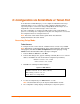

Configuration Using Web-Manager
MatchPort b/g™ User Guide 38
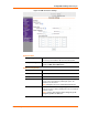
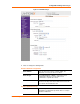
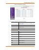
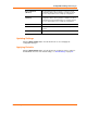
Figure 4-13. Configurable Pins Settings
2. Configure or modify the following fields for each pin:
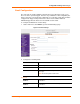
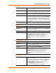
Function
From the drop-down list, select the purpose of the specified
pin. See Configurable Pin Functions for a description of each
available function.
Direction
Select whether the pin inputs or outputs.
Trigger Input
Select whether the GPIO input signal is to be used as a trigger
condition for email.
Active Level Select the signal active level (Low or High).
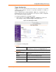
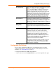
Configurable Pin Functions
General Purpose I/O
Monitors input or controls output by means of the 77F0 port.
Modem Ctrl Channel 1 In
Allows for control of the connection (and disconnection) of
channel 1.
Modem Ctrl Channel 1
Out
Indicates a connection is established on channel 1.
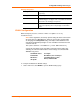
Modem Ctrl Channel 2 In
Allows for control of the connection (and disconnection) of
channel 2.
Modem Ctrl Channel 2
Out
Indicates a connection is established on channel 2.
Serial Channel 1 Status
LED
Indicates channel 1 status and extended diagnostics when the
Diagnostics LED is lit.
Serial Channel 2 Status
LED
Indicates channel 2 status and extended diagnostics when the
Diagnostics LED is lit.
Diagnostics LED
Indicates errors and configurations.