
User guide


Ethernet TCP/IP Card Installation Manual - Installation 5
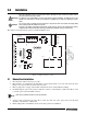
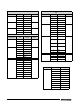
Figure 2-3. Ethernet Card Serial Wiring
4. Use cable ties to secure loose cables inside the
enclosure away from high voltage circuits
2.1.2 External Ethernet Cabling
Configure external Ethernet cabling using either the
RJ-45 connector (LX1) or the hardwire connection to
J4 on the Ethernet card. When using an external RJ-45
connector, we recommend using a DNET 1 network
surge suppressor (PN 72682) wired through a cord
grip with the RJ-45 socket left outside of the
enclosure.
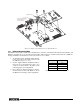
2.1.3 Reassembling The Enclosure
1. Once cabling is complete, position the
backplate over the enclosure and reinstall the
backplate screws. Use the torque pattern
provided in the indicator’s installation manual
to prevent distorting the backplate gasket.
2. Ensure no excess cable is left inside the
enclosure and tighten the cord grips.
3. Reconnect power to the indicator.
Contact factory for washdown option.
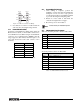
2.1.4 Ethernet Option Parts Kit Contents
Table 5-4 shows the parts kit contents for PN 71986.
shows the parts kit contents for PN 77205.
Pin Signal
1Gnd
2TxD+
3TxD-
4RxD+
5RxD-
6Gnd
Table 2-5. Ethernet Card J4 Pin Assignment
Ether net
Car d
Indicator
Port
TXD
RXD
GND
TXD
RXD
GND
PN Description
14822 Screws, 4-40NCx1/4 (2)
15631 Cable tie, 3 in nylon (2)
54325 Unshielded cable, grey 60 in (1)
78269 RJ-45 cable, 5 in (1)
83267 Ethernet card, RS-232/Ethernet (1)
72763 Ethernet CD (1)
Table 2-6. PN 71986 Parts Kit Contents
PN Description
14822 Screws, 4-40NCx1/4 (2)
15631 Cable tie, 3 in nylon (2)
54325 Unshielded cable, grey 60 in (1)
78269 RJ-45 cable, 5 in (1)
72696 Cable, 3-pin to blunt 3-wire (1)
83267 Ethernet card, RS-232/Ethernet (1)
72763 Ethernet CD (1)
Table 2-7. PN 77205 Parts Kit Contents
Note