Ethernet TCP/IP Interface For Rice Lake Indicators Installation and Configuration Manual To be the best by every measure 72117
Contents About this Manual .................................................................................................................................... 1 1.0 Introduction.................................................................................................................................. 1 2.0 Installation ................................................................................................................................... 2 2.1 Ethernet Card Installation . . . . . . . . . .
Rice Lake continually offers web-based video training on a growing selection of product-related topics at no cost. Visit www.ricelake.com/webinars.
About this Manual This manual is intended for use by service technicians responsible for installing the Ethernet card option in Rice Lake indicators. 1.0 Authorized distributors and their employees can view or download this manual from the Rice Lake Weighing Systems distributor site at www.ricelake.com. Introduction The Ethernet card option comes in two sizes. The larger size (PN 83267; see Figure 2-1 on page 2) can be used in the 920i, 820i, and 720i.
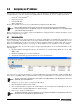
2.0 Installation Rice lake indicators have no on/off switch. Before opening the unit, ensure the power cord is disconnected from the power outlet. Warning The Ethernet card should NOT be used to communicate between buildings. The Ethernet port is not suitable for connection to circuits used outside the building and is subject to lightning or power faults. Use a wrist strap to ground yourself and protect components from electrostatic discharge (ESD) when working inside the indicator enclosure.
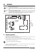
ET RES SW1 Diagnostic Lights LX1 J1 Patch cable (Only use if terminating Ethernet cable to J4 screw terminals) J3 J2 EGnd + TxD TxD + RxD J4 RxD EGnd Figure 2-2. Ethernet Card Installation onto 920 CPU Board 2.1.1 Ethernet Card Serial Port Wiring The Ethernet card requires an RS-232 communications connection to the Rice Lake indicator. The indicator and Ethernet card must be set to the same baud rate (Rice Lake indicators’ default serial baud rate is 9600.
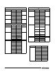
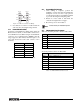
. 920i 720i Connector Pin J11 1 Gnd 2 J9 J10 Signal Port Connector Pin 1 J3 1 CLK RS-232 RxD 2 +5V 3 RS-232 TxD 3 GND 1 GnD 4 DATA 2 RS-232 RxD 1 GND 3 Rs-232 TxD 2 RS-232 RxD 1 GnD 3 RS-232 TxD 2 RS-232 RxD 4 RS-232 RTS 3 RS-232 TxD 5 RS-232 CTS 6 GND 1 RS-422/485 Y 2 RS-422/485 Z 3 RS-422/485 B 4 RS-422/485 A 5 +6V 6 GND 1 GND 2 RS-232 RxD 3 RS-232 TxD 4 20mA OUT 3 J2 4 820i Connector Pin J9 1 CLK 2 +5V 3 GND J10 J11 Signal
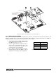
2.1.3 Ethernet Card Indicator Port TXD TXD RXD RXD GND GND Figure 2-3. Ethernet Card Serial Wiring Note 4. Use cable ties to secure loose cables inside the enclosure away from high voltage circuits 2.1.2 External Ethernet Cabling Configure external Ethernet cabling using either the RJ-45 connector (LX1) or the hardwire connection to J4 on the Ethernet card.
3.0 Assigning an IP Address The following section covers the steps required to assign an IP address. The IP address must be assigned and configured before a network connection is available. There are four methods, any one of which can be used: • Lantronix® DeviceInstallerTM • Network port login • Command Prompt • Web Configuration Both of these installer tools are located on the Ethernet Configuration CD, PN 72763. Refer to www.lantronix.
3.2 Network Port Login The network port login provides a way to make a telnet connection to the network port (9999). This ARP method is available under UNIX and Windows-based systems. 1. Set a static ARP with the desired IP address using the hardware address of the scale. The address is printed on a label attached to the Ethernet card. In order for the ARP command to work in Windows®, the ARP table on the PC must have at least IP address defined other than its own.
2. To statically enter the IP address, type arp-s (your IP address) (mac address shown on the card). Refer to the first example shown in Figure 3-2 7. 3. Use a telnet session to activate the address by typing telnet (your IP address) 1. The telnet connection will time out and fail, but the address will be activated. 4. You can view the address in your arp table by typing arp -a. This will list the arp table and you will see your IP address and its mac address, and it will be listed as a static entry. 5.
Figure 3-4. Web Configuration Serial Settings Refer to the Lantronix User’s Guide for further instructions on Ethernet configuration by Telnet. Note Rice Lake indicators can act as an Ethernet – TCP/IP to RS-232 converter. The converter can act as a server and accept an incoming connection, or, through a special serial command prepended to a serial transmission, it can connect to remote servers.
4.0 WLAN Installation and Configuration Note Before installing this option, you must contact your IT administrator to obtain network communication protocol codes and have a RS-232 communications cable or regular comm port cable available to run between your PC and the indicator while installing and setting up the wireless network. The optional Lantronix® WiPort™ (WLAN - Wireless Local Area Network) wireless networking device comes in two sizes.
4.1 Enclosure Disassembly The indicator enclosure must be opened to install the WLAN option card and antenna and to connect cables for installed option card. Warning Before opening the unit, ensure the power cord is disconnected from the power outlet. 1. Disconnect power to the indicator. 2. Place the indicator face-down on an antistatic work mat. 3. Remove the screws that hold the backplate to the enclosure body, then lift the backplate away from the enclosure and set it aside. 4.
Approx 1” of antenna exposed Figure 4-3. Location of WLAN antenna 3. Tighten the cord grip. Option cards are recognized when the unit is powered on. 4.4 Wireless Configuration via Serial Mode You must configure the WLAN card so that it can communicate on your network. WiPort (WLAN) is configurable using a PC and a terminal program (like Windows XP HyperTerminal) to access the device serial port locally.
4.6 WLAN Card Configuration 1. Select the HyperTerminal program on the PC. 2. Enter a name and choose an icon for the connection, then click OK. Figure 4-5. HyperTerminal connection description screen 3. Select a Connect To option. Select the comm port you have connected your serial cable to and click OK. Figure 4-6. Connect To screen 4. Comm port properties must be set as shown in the following screen.
Figure 4-7. Comm Port Properties screen The WLAN configuration port uses the following settings: • Baud Rate: 9600 • 8 Bits • No parity • • 1 Stop Bit No Flow Control 5. Make the changes and click OK to save the changes. 6. Reset the WLAN option card by pressing the manual reset button shown in Figure 4-8, and immediately upon release, enter three lowercase x characters (xxx) at the same time. Manual Reset Button Figure 4-8.
Upon a successful connection, the following information is displayed. Figure 4-9. Display Information for Setup Mode 7. To enter Setup Mode, press Enter within five seconds. Note that the connection will fail if Enter is not pressed within the five second time limit. The configuration settings display, followed by the setup menu options. If this happens, repeat Step 5. 8. Select an option on the menu by entering the number of the option in Your Choice? field and press Enter.
Select 0 for your choice and press Enter. 10. The next menu choice is Network Name as shown below. Figure 4-12. Network Name Screen Enter your wireless network name as your menu choice and press Enter. This identifies the network that the wireless option will run on. 11. The next step is to select a level of security as shown in Figure 15. Figure 4-13. Security Level Select Screen Security levels include: • 0 = None • 1 = WEP (Equivalency Protection) • 2 = WPA Select 1 and press Enter. 12.
Authentication choices are: • 0 = open/none • 1 = Shared Select 0 = open/none and press Enter. 13. Select the correct encryption next. Choices are WEP64 and WEP128 as shown below. Select 1 = WEP64 as the default parameter and press Enter. Figure 4-15. Encryption Screen 14. Next, it asks to display current key? Press N and press Enter. Figure 4-16. Display Current Screen 15. Select Yes (Y) for the “display current key” option. This prompt shows the currently configured key/ passphrase. Figure 4-17.
17. The screen automatically goes to end the screen which gives the choice to Save and Exit (9) and is shown below. By selecting that choice, and pressing Enter, the WLAN parameters are saved and the screen becomes grayed out as is shown below. Figure 4-18. Save and Exit Screen Once all of the data is saved, you must switch the jumpers back to the OFF position (Figure 5) to exit out of the configuration mode. Now you can access and view all wireless data on the PC. 4.
4.9 WiPort Technical Data Category Description CPU, Memory Lantronix DSTni-EX 186 CPU, 256 KB zero wait state on chip SRAM, 2048 KB flash, 16 KB Bott ROM Firmware Upgradeable via TFTP and serial port Reset Circuit Reset In is low active. Minimum reset pulse width is 2 ms at IIL = -500 aA Serial Interface CMOS (Asynchronous) 3.
4.10 WiPort Disclaimer This equipment has been tested and found to comply with the limits for a Class B digital device, pursuant to Part 15 of the FCC rules. These limits are designed to provide reasonable protection against harmful interference in a residential installation. This equipment generates, uses, and can radiate radio frequency energy and, if not installed and used in accordance with the instructions, may cause harmful interference to radio communications.
5.0 920i/iQube Email Setup Error conditions generate a displayed error message if the iQube is connected to a 920i which, with an Ethernet card, can be configured to email the alert message to a specified address. 5.1 Configuration For email to work, both the 920 port (wired to) and the Ethernet serial port (wired to) must be both set to default values or are set to the same baud, bits, parity, etc. Once this is done, follow the steps below: 1.
Other common problems occur within mail servers. Local email clients use the Post Office Protocol version 3 (POP3), an application-layer Internet standard protocol, to retrieve email from a remote server over a TCP/IP connection. If the 920i’s IP address isn’t allowed to relay (send) mail, the message could be rejected. The email server needs to be manually configured to allow the 920i to do this.
Using the Email Test Server 1. 2. 3. 4. Visit http://www.ricelake.com/downloads to download the SMTP Test Server program. Once the Email Test Server program is installed, set the appropriate server address on the 920i. Intentionally generate an error. The Email Test Server program will show data sent from the 920i, confirming whether the email is sent successfully. Figure 5-2. SMTP Test Server Alternatively, you can follow these steps: 1. Ping the 920i to ensure you have network connectivity. 2.
6.0 Streaming with Ethernet When using a Lantronix TCP/IP module in Rice Lake indicators which are capable of streaming, stream data can be sent to a 920i as a serial scale using a corporate Ethernet backbone. This is referred to as serial tunneling. This section provides a brief overview of how to use serial tunneling. For more extensive information, refer to the following link: • http://ts.lantronix.com/tutorials/serial-tunnel/Serial_Tunneling.html Note 6.
Figure 6-1.
Figure 6-2. Sender setup Note The parameters are set using a telnet connection within DeviceInstaller. We can see that the only parameters changed from default (other than baud rate) is the port for the receiver to look for, the ConnectMode to adjust each for its own function, Listen or Sender, and the Remote IP in the sender to direct the packet to the correct IP address. These units, once set up, will do an auto connect as soon as either they return to weigh mode or after a power cycle.
7.0 Ethernet Specifications Protocols Supported Power Requirements Rice Lake indicators: TCP/IP, UDP/IP, ARP, ICMP, SNMP, TFTP, Telnet, DHCP, BOOTP, HTTP, and AutoIP 6v – supplied by indicator Environmental Device Support Operating Temperature 5 to +50°C (41 to 122°F) Storage Temperature –40 to +60°C (–40 to 151°F) Supports any asynchronous serial device with 7- or 8-bit data, with or without parity requiring Ethernet access Weight Network Interface 0.8 lb (0.
8.0 Appendix A PIN Function Color 1 TX+ White/Orange 2 TX- Orange 3 RX+ White/Green 4 Blue 5 White/Blue 6 RX- Green 7 White/Brown 8 Brown Table 8-1. Pin Assignments Figure 8-1. RJ-45 Connector Figure 8-2. Standard Patch Cable 28 Ethernet TCP/IP Card Installation Manual Figure 8-3.
9.0 Glossary 100Base-T Standard for 100 Mbps Ethernet (IEEE 802.3) over unshielded twisted pair (UTP) cable. Commonly known as Fast Ethernet. 10Base-T Standard for 10 Mbps Ethernet (IEEE 802.3) over unshielded twisted pair (UTP) cable. ASCII American Standard Code for Information Interchange - a 7 bit code used to represent text control codes. CAT-5 Category 5 - UTP cable rated for data rates up to 1000 Mbps. CAT-6 UTP cabling that is rated for up to 1000 Mbps.
LAN Local Area Network - A communications network designed to connect computers in a limited geographic area (typically under 10 km). LRC Longitudinal Redundancy Check. MAC Media Access Control - the protocol responsible for controlling which device can talk on the network at any given time. Mbps Megabit per second - a data transfer rate of 1 million bits per second. Manchester Encoding A digital signaling scheme that uses signal transistors rather than levels to indicate data: (i.e.
UTP Unshielded Twisted Pair. UART Universal Asynchronous Receiver Transmitter. VLAN Virtual Local Area Network - a collection of computers on a LSN that act as a self-contained group. VPN Virtual Private Network. VRC Virtual Redundancy Check. WAN Wide Area Network - a communications network designed to connect computers across the country or world.
Ethernet Interface Limited Warranty Rice Lake Weighing Systems (RLWS) warrants that all RLWS equipment and systems properly installed by a Distributor or Original Equipment Manufacturer (OEM) will operate per written specifications as confirmed by the Distributor/OEM and accepted by RLWS. All systems and components are warranted against defects in materials and workmanship for two years. RLWS warrants that the equipment sold hereunder will conform to the current written specifications authorized by RLWS.
PN 72117 02/11