IQ6200/6500 Counting Scales Installation Manual 32224
Contents About this Manual ................................................................................................................................. 1 1.0 Introduction .............................................................................................................................. 1 1.1 Scale Resolution .............................................................................................. 2 1.2 Choosing the Best Sample ............................................................
5.0 Data Storage ........................................................................................................................... 15 5.1 Programming Unit Weight for a Code Number in Weighing Mode ................ 16 5.1.1 5.2 Check or Change Code Number Data ........................................................... 16 5.3 Delete Items from Memory ............................................................................ 17 5.2.1 5.3.1 5.3.2 5.3.3 5.3.4 5.3.5 5.3.6 6.
About this Manual This manual contains operating procedures for the IQ6200, IQ6500, and IQ6500 dual counting scales and provides the user with all the information necessary for set-up and operation. This manual is organized based on the procedures you will likely follow when setting-up and using your counting scale. When information is applicable to all three scales you will see the term “IQ6200/6500”. If information is specific to only one type of scale, a single name “IQ6200” or “IQ6500” appears.
1.1 Scale Resolution Counting scales specify two types of resolution: • Weight (or external) • Counting (or internal) Weight resolution is displayed in increments of the full scale capacity which is divided into weight increments. For example, a 5-lb. scale divided into 10000 weight increments would display weight with 0.0005 lb. incremental elements (10000 divisions x 0.005 lb. = 5.0 lbs.). Counting resolution is based on the internal resolution of the scale.
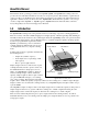
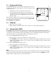
2.3 Unlocking and Locking Your IQ6200/6500 scale is delivered in a locked position to prevent damage to the load cells during shipment. Use the following procedure to unlock the scale. 1. On underside of scale, use wrench to remove nut (1). 2. Use allen wrench provided with scale to turn bolt (2) in a counterclockwise direction and remove. Two nuts and two bolts must be removed on an IQ6500 dual scale as shown in diagram to right.
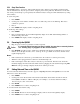
2.5.1 Sleep Time Function The IQ6200 includes a “sleep time” function that turns the scale off after a preset number of minutes if the scale is undisturbed (no keys are pressed and no weight is placed on the platform). This function works with AC or DC power and helps to prolong battery life when the battery is being used. The default (factory) setting is five minutes. To set the sleep time: 1. Press MODE. 2. Use keypad to enter number of minutes, 01 to 99, until scale powers down.
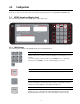
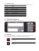
3.0 Configuration Sections 3.1 and 3.2 show and describe the keypads and display panels for the IQ6200 and IQ6500 scales. 3.1 IQ6200 Keypad and Display Panel The following figure shows the IQ6200 display panel and keypad. IQ lb 6200 WEIGHT . ZERO . . . . . GROSS RECOMP TARE INSUFF. MEMORY per 1000 pcs UNIT-WEIGHT . OUT . . . . IN PROG. kg LOW BAT. kg lb . ON OFF MOVEMENT 7 8 9 - 4 5 6 + 1 2 3 * 0 . CLEAR # MODE lb PIECES QUANTITY TARE RE ZERO 3.1.
RE ZERO Rezero Eliminates weight from the Weight display with no tare in the system and causes it to show a true 0. The rezero button will not function when the indicator is in motion. Tare TARE Zeroes the weight display by placing a displayed weight into the tare register. The system must be in a standstill condition before a tare can be registered. The tare register is normally used to store a value such as a container weight. Pieces PIECES Sets the number of sample pieces.
3.1.2 IQ6200 Indicator Lamps Use the following table to identify display indicator lamps that may be illuminated during operation.
PART# + DATE 3.2.2 – / PART# Used to subtract parts from an accumulation operation or view an alternate part number. + / DATE Used to add parts from an accumulation operation or set the date and time in the program mode. IQ6500 Indicator Lamps Use the following table to identify display indicator lamps that may be illuminated during operation.
3.3.3 Digital Tare Entry 1. Press 0, then TARE to reset any tare. 2. Press REZERO. After resetting, displays show zero. 3. Use keypad to enter number 0.2, then press TARE. For digital tare entry, decimal must be in appropriate place as they would be displayed in Weight display. For example, .250 would be entered as “0.250”, not “.250”. The Weight display shows weight entered with a negative sign indicating that it is a tare weight. 3.3.4 Weight, Unit Weight, and Quantity Display 1.
4.0 Operating Instructions This section provides detailed instructions for operating your IQ6200/6500. Basic to all counting procedures is the requirement to establish the average unit weight of the parts to be counted. Typically this is done by taking a representative sample quantity of the parts, determining the total weight of that sample, and then obtaining the average unit weight by computation. The IQ6200/6500 does this all in one step.
1. Determine the unit weight by the normal sampling procedure. 2. If the initial sample fits the recompute criteria, then an additional group of parts, usually one to three but up to eight times the initial sample size, may be placed onto the platform. Any number of parts will suffice if the recompute light remains on. If the light goes out, remove some parts until the light is on again. 3. After placing the additional parts onto the platform, press PIECES.
4.3 Negative Parts Counting This feature counts the parts quantity as you remove them from a bulk container on the platform (see SPEC08). To perform negative parts counting: 1. Place the container (with parts) on the platform 2. Press REZERO. 3. Take a 10-piece sample from the container and press PIECES (or key in the number if other than 10 and then press PIECES). The Quantity display shows a count of 10 (or quantity entered). 4.
Setpoint 1 in Example 3 is the under setpoint and sounds intermittently until it reaches the over setpoint (2). Example 3 SPEC16 0100 Setpoint 1 = 500 pieces Setpoint 2 = 400 pieces 0 Intermittent No Buzzer Buzzer |<-––––——————> |_______________ 400 500 To program general setpoints: 1. Press MODE. The Weight display shows ProG. 2. While holding REZERO, press + key (release REZERO). The Quantity display shows SEt 1. 3. Enter target weight or count.
4.7 Sample and Count 1. Verify desired sample scale is selected (generally scale 1) and all displays are showing 0. If Unit Weight display does not show 0, press 0 and then UNIT WEIGHT. If Weight display does not show 0, press REZERO. 2. Add samples, being sure to enter number of samples if other than 10. 3. Press PIECES and wait for a count to appear. 4. Enter tare weight of container and add a full container of parts. 4.
5.0 Data Storage Code numbers allow you to store information for the weighing applications you use the most. This eliminates the need to continually re-enter data for weighing applications that are used on a regular basis. You can program up to 100 code numbers on your IQ6200/6500. Each code number can store the following data: • • • • • • Code or ID number Tare weight Unit weight Part number Inventory Setpoint A form designed to assist you when entering code number data appears in Section 12.1.
5.1 Programming Unit Weight for a Code Number in Weighing Mode 1. In weighing mode, key in code number and press #. The displays respond with preprogrammed information. If code number entered has not been programmed into memory, Quantity display shows “not F”. If code number is to be entered into memory, press # to enter it, or press CLEAR to clear display. 2. Enter unit weight (if known) with keypad. If unit weight is not known, use sample procedure at beginning of this section. 3. Press UNIT WEIGHT.
5.3 Delete Items from Memory The following sections contain procedures for deleting items from the memory of your IQ6200/6500. 5.3.1 1. 2. 3. 4. 5.3.2 Deleting a Particular Code Press MODE to enter program mode. Enter code to be deleted. Press #, then press CLEAR. Press MODE to return to weighing mode. The selected code is deleted. Deleting Entire Memory Notice: This procedure erases all unit weights, inventories, setpoints, tare weights, code numbers and part numbers. 1. 2. 3. 4. 5.3.3 1. 2. 3. 4.
6.0 Setting Configuration Setting configuration allows you to easily modify the functionality of your IQ6200/6500. Use the tables in this section to view the options you can modify. For example, if you wanted the auto recomputation function to work on your IQ6500, you would go to the IQ6500 spec table and find SPEC08. Go across the row and see that bit 1 of SPEC08 controls the recomputation function. The default configuration for SPEC08 is 1000, which means that the auto recomputation function is off.
6.2 Configuring Display Resolution SPEC04 sets the display resolution for the IQ6200 and IQ6500 scales. The following tables show the display resolutions available for each scale capacity. Units are switchable from lb. to kg. and can be programmed to primarily weigh in lb., kg., g., oz., ozt, or dwt. IQ6500 scales with a capacity of 0.5 to 100 lbs. have both internal and external mounting capabilities, while scales from 250 to 50000 lbs. are external only. 6.2.
6.3 IQ6200 Configuration The following table shows the IQ6200 grads and decimal values for spec numbers 00 through 03. Spec No. Grads Bit 3 Bit 2 Bit 1 Bit 0 1 0 0 0 1 2 0 0 0 0 5 0 0 1 0 10 0 0 1 1 Decimal Bit 3 Bit 2 Bit 1 Bit 0 0 0 0 0 0 0.0 0 0 0 1 0.00 0 0 1 0 0.000 0 0 1 1 0.0000 0 1 0 0 SPEC00 SPEC01 SPEC02 Not Used SPEC03 Not Used The following table shows the values for IQ6200 spec numbers 04 through 22. Spec No.
6.4 IQ6500 Configuration The following table shows the grads and decimal values for IQ6500 spec numbers 00 through 03. Values for SPEC numbers 04 through 22 are shown on the following page. Spec No. Grads Bit 3 Bit 2 Bit 1 Bit 0 SPEC00 (Scale #1) 1 0 0 0 1 2 0 0 0 0 SPEC02 (Scale #2) 5 0 0 1 0 10 0 0 1 1 Decimal Bit 3 Bit 2 Bit 1 Bit 0 0 0 0 0 0 0.0 0 0 0 1 0.00 0 0 1 0 0.000 0 0 1 1 0.
The following table shows the values for IQ6500 spec numbers 04 through 22. Spec No.
6.5 IQ6500 Second Channel Setup For second channel operation, configure the unit using the spec codes. SPECs 02, 03, and 04 are used for second channel setup. Use the IQ6500 display resolution chart (Section 6.2.2) in conjunction with the IQ6500 spec tables in Section 6.4 to determine settings for SPEC02 (Grads) and SPEC03 (Decimal). For example, you would perform the following steps if you were attempting to connect a 2000 lb. capacity external scale to your IQ6500. 1.
7.0 Calibration The calibration procedure maintains the scale accuracy within specifications and can serve as a performance test procedure. Your IQ6200/6500 scale should be on for 30 minutes before attempting to calibrate. Use the following procedure to calibrate: 1. To enter calibration mode, press and hold REZERO while entering 8 7 1 5 on the keypad. The Quantity window displays the raw count. If the unit will not allow you to enter calibration mode, the calibration lock-out switch may be ON.
8.0 Display Messages The following table shows the messages that are displayed during operation of the IQ6200/6500. Message Description —Add XX All CLEAr C XX CH XX CLEAr dA - XX - XX - XX (IQ6500 only) (printer) Comm on (IQ6500 only) (printer) Comm off (IQ6500 only) Err - (IQ6500 only) InSUFS InVEnt CLEAr Lo-Err L-YEAr (IQ6500 only) P-no CLEAr P-oFF (IQ6200 only) ProG.
9.
9.2.2 Baud Rate Selection The baud rate range is 300 to 9600 and is adjusted by setting one of six jumpers on the board TPB-1670. Only one jumper may be installed at any time. Jumper JP-1 JP-2 JP-3 JP-4 JP-5 JP-6 9.2.
9.2.6 RS-232 Installation Instructions Use the following procedure to install an RS-232 connection on your IQ6500. 1. 2. 3. 4. 5. 6. 7. 8. 9. 10. 11. Remove platter and four screws at center of platter support. Remove platter support. Remove case cover by removing six screws on top and two screws under front edge of scale. Unplug connectors (A and B). Remove two screws (1) from each A/D board. Lift each board out and gently place them on top of load cell.
9.3 IQ6500 Printer Configuration With the RS-232 option installed you can use a ticket, tape, or bar code label printer to record scale activity. The IQ6500 allows you to print from the weighing mode or program mode. You would print from the weighing mode when performing an actual counting operation, while printing from the programming mode is used to check for item memory. Both modes produce a print ticket or tape. The * key is used to activate the print function. 9.3.
9.3.3 Sample Tickets The following examples show weighing mode and program mode tickets from a TM-300 tape printer. The TM-290II, TM-295, SP-2000 and SP2200 printers all provide the ticket format as the TM-300. JAN. 16, 1995 / 9:00 AM JAN. 16, 1995 / 9:00 AM ID. CODE: 111 ID. CODE: 111 P/N: 0264FFD78901 P/N: 0264FFD78901 GROSS WEIGHT: 0.1016 GROSS WEIGHT: 0.1016 TARE WEIGHT: 0.0000 TARE WEIGHT: 0.0000 NET WEIGHT: 0.1016 NET WEIGHT: 0.1016 UNIT WT/1000: 0.1000 UNIT WT/1000: 0.
9.4 Setpoint Outputs Two setpoint outputs are available as open-collector transistor transistor logic (TTL) level outputs for driving relays on the RS-232 option. The outputs are available on the circular connector on the rear of the scale marked “setpoint” and are configured by setting SPEC15 bit 2 and SPEC16 bits 0–3. See Section 6.0 for more information about configuring SPEC codes.
9.5 IQ6200 Battery Pack Installation 1. 2. 3. 4. 5. Gently lift and remove platform. Remove four screws at center of platform support. Remove platform support. Remove six screws from top covers (two in keypad section and four in main). Remove two screws from front underside of scale (one in each corner) and remove main cover. Remove two screws at top of each battery support (1). Note placement of ground wires (2) for reinstallation. 6.
10.0 Maintenance This section contains information about IQ6200/6500 maintenance. Preventive maintenance consists of periodically cleaning the external surfaces of the scale and should be performed as often as operating conditions warrant. Service or repair should be attempted by qualified personnel only, and only when it has been positively determined that the counting scale requires such service. All service should be done in a clean, dry, dust-proof area.
10.3 Load Cell Replacement Procedure 1. Disconnect power to scale. 2. Remove platter. 3. Remove four spider assembly screws, then remove spider assembly. For dual platter scales, repeat for second spider assembly. 4. Remove two bottom and two top screws holding front panel. 5. Slide front panel forward to disengage tabs on cover. 6. Remove plastic cover (4 screws) under spider assembly. 7. Remove ground cables (one screw per assembly). 8. Remove hold-down screws from load cell assembly.
11.0 Specifications The following sections list specifications for the IQ6200 and IQ6500 counting scales. See Section 6.2 for display resolution information. Technical specifications for the IQ6500 dual scale are the same as the single platform IQ6500 with the exception of the platform size. 11.
12.0 Appendix 12.1 Code Number Form You may want to make photocopies of the following form and use them to record information for each code number prior to entering the information in the memory of your IQ6200/6500. 1 2 3 4 5 6 7 8 9 10 11 Code or ID Number Tare Weight (include decimal) Unit Weight (include decimal) Part Number Inventory Setpoint Quantity 12.2 Character Code List The following table contains two-digit numerics used to enter alphanumeric part numbers.
12.3 Eltron Printer Interface The Eltron printer interface option, PN 41278, allows the IQ6500 counting scale to connect to all Eltron printers except models LP 2022 and LP 2042. The factory-installed option consists of a custom EPROM for the IQ6500 and a 25-to-9 pin D-SUB interface cable, PN 41279. The baud rate for the IQ6500 is set to 9600 bps by changing the jumper as shown in the figure below.
IQ6200/6500 Limited Warranty Rice Lake Weighing Systems (RLWS) warrants that all RLWS equipment and systems properly installed by a Distributor or Original Equipment Manufacturer (OEM) will operate per written specifications as confirmed by the Distributor/OEM and accepted by RLWS. All systems and components are warranted against defects in materials and workmanship for one (1) year. RLWS warrants that the equipment sold hereunder will conform to the current written specifications authorized by RLWS.