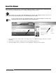
Counterpart ® Counting Scale Indicator Version 2.
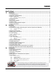
Contents About This Manual ................................................................................................................................... 1 1.0 Introduction.................................................................................................................................. 2 1.1 Standard Features . . . . . . . . . . . . . . . . . . . . . . . . . . . . . . . . . . . . . . . . . . . . . . . . . . . . . . . . . . . . . . 2 1.2 Capacities and Resolutions . . . . . . . . . . . .
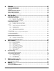
.0 Calibration ................................................................................................................................. 48 4.1 4.2 4.3 4.4 4.5 4.6 Front Panel Calibration . . . . . . . . . . . . . . . . . . . . . . . . . . . . . . . . . . . . . . . . . . . . . . . . . . . . . . . . . Five-point linearization . . . . . . . . . . . . . . . . . . . . . . . . . . . . . . . . . . . . . . . . . . . . . . . . . . . . . . . . . Rezero . . . . . . . . . . . . . . . . . . . . . . . . . . .
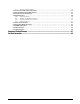
9.2.1 9.3 9.4 9.5 9.6 Using the P EDP Command . . . . . . . . . . . . . . . . . . . . . . . . . . . . . . . . . . . . . . . . . . . . . . . . . . . . . . . . 76 Continuous Output (Stream) Format . . . . . . . . . . . . . . . . . . . . . . . . . . . . . . . . . . . . . . . . . . . . . . . Demand Output Serial Data Format . . . . . . . . . . . . . . . . . . . . . . . . . . . . . . . . . . . . . . . . . . . . . . . Custom Stream Formatting . . . . . . . . . . . . . . . . . . . . . . . . . . . . . . . . . .
Rice Lake continually offers web-based video training on a growing selection of product-related topics at no cost. Visit www.ricelake.com/webinars.
About This Manual This manual is provided for the use of trained and qualified installers of counting scales, and represents the correct, safe and recommended methods for setting up and using the Counterpart®. This manual can be viewed and downloaded from the Rice Lake Weighing Systems web site at www.ricelake.com. Rice Lake Weighing Systems is an ISO 9001 registered company.
1.0 Introduction The Counterpart offers practical solutions for a full range of precision counting applications. A bright LCD display enables operators to easily view quantities and alphanumeric text messaging displays part numbers to verify descriptions and correct part called from memory. One hundred and fifty (150) item memory and two RS-232 ports and Ethernet enable the Counterpart to provide real-time data collection and position it for the future growth of your business.
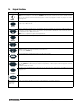
1.4 Keypad Functions Key POWER Function Turns the Counterpart unit on/off. NOTE: If the PC1 jumper is set to SW, the POWER button must be used to turn the unit on and off. If the PC jumper is set to ON, the unit will automatically power on when it’s plugged in and the only way to turn it off is to unplug power. Enters Menu mode, allowing configuration if the Audit jumper is in the “ON” position. Also used as an “escape” key in Menu mode.
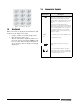
1.6 Annunciator Symbols Annunciator Zero (Center of Zero) While in gross weight display mode, this LED indicates that the current displayed weight reading is within +/-0.25 display divisions of the acquired zero, or is within the center of zero band. When in the net weight display mode, it indicates that the current net weight reading is within +/-0.25 display divisions of the center of net zero.
1.7 Softkey Setup Softkeys offer additional ways to access features associated with the Counterpart . To access the softkey setup parameter, go to Menu -> Setup -> Config -> Feature -> Softkeys. Select information for each softkey and press TARE (Enter) key after each entry and then press SaveExit softkey. To exit back out of the unit, press the MENU SETUP key twice without saving changes.
2.0 Installation Counterpart is available in different configurations from just the indicator display to the display and counting scale combined together as a unit. This section contains instructions on unpacking and assembly, leveling, making power connections, load cell wiring, wiring standard serial port, optional network communications, wiring optional digital outputs, optional backup battery operation, and power-up sequence. Assembly drawings and replacement parts lists are also included.
2.2 Scale Base Assembly (if purchasing the scale base separate from indicator) Caution Do not turn the scale upside down. Always work with the scale on its side. Damage to the load cell can occur if the scale is turned upside down. Set up the scale on a stable, level surface. 2.2.1 Locking and Unlocking The Counterpart scale base is delivered in a locked position to prevent damage to the load cells during shipment.
2.3 Enclosure Disassembly The Counterpart indicator enclosure must be opened to connect cables for load cells, communications, and digital inputs/outputs. Warning Before opening the unit, ensure the unit is turned off and the power cord is disconnected from the power outlet. The power outlet must be located near the indicator to allow the operator to easily disconnect power to the unit. Ensure power to the indicator is disconnected, then place the indicator on an antistatic mat.
2.7 Cable Grounding Except for the power cord, all cables should be grounded against the scale enclosure. Do the following to ground shielded cables. • Use the lockwashers, clamps, and kep nuts provided in the parts kit to install grounding clamps on the enclosure studs. Install grounding clamps that will be used; do not tighten nuts. • Route cables and grounding clamps to determine cable lengths required to reach cable connectors.
2.7.2 Digital I/O The Digital I/O can be configured as either digital inputs or digital outputs as determined by the Digital I/O menu (see Section 3.6.5 on page 35). The inputs are active (on) with low voltage (0 VDC) and can be driven by TTL or 5V logic without additional hardware. Use the Digital I/O menu (see Section 3.6.5 on page 35) to configure the digital inputs. LEDs on the CPU board light when digital inputs are active (see Figure 2-4).
2.9 CPU Board Removal If you must remove the Counterpart CPU board, use the following procedure: 1. Disconnect power to the scale. 2. Disconnect power supply cable from connector J12 on the Counterpart CPU board. 3. Disconnect the wires at the following connectors: J1, J2, J3, J4 and J5 and J13 if equipped. 4. Remove the six screws connecting the CPU board, then lift the board out of the enclosure. To replace the CPU board, reverse the above procedure.
6. Using the supplied nuts, secure battery pack to enclosure using a 5/16” nut driver. Unplug existing power off the CPU board and plug in battery plug J1 on battery CPU. Run cable from battery pack to J12 on main CPU board. Screw bracket into enclosure (only one side shown) Figure 2-6. Secure Battery Pack in to Enclosure 7. Run cable over to power plug J12 on the Counterpart CPU board. Figure 2-7. Connect Power Plug on to J12 on CPU Board 8.
5. Make connections to the option card as required. Use cable ties to secure loose cables inside the enclosure. When installation is complete, reassemble the enclosure as described in Section 2.8. ON +3.3v SW PC1 +5 R WD1 P U G N M C3 PWR Port 3 LED Power Supply Display Backlight Display connector LED LED JP1 JP2 JP3 JP4 JP5 JP6 RST RS-232 Connectors ISP Ethernet Connector Figure 2-8. Counterpart CPU Board Jumper Description JP1/JP2 JP3/JP4 Jump excitation to sense.
2.13 Bracket Assembly Connecting Indicator to Scale Base The Counterpart scale comes with an easy bracket assembly that conveniently hooks the indicator head to the scale base. That assembly is found in the scale base box and is shown below. Figure 2-9. Bracket Assembly Kit for the Counterpart Scale Base Use the following steps to attach the indicator to the scale base. Caution Do not turn the scale upside down. Always work with the scale on its side.
2.
Figure 2-14.
Figure 2-15. Counterpart Dimensions Figure 2-16.
3.0 Configuration 3.1 Front Panel Configuration To set up and configure the Counterpart counting Scale, you will use the MENU key on the front panel. The indicator is defaulted at the factory with the audit trail jumper (JMP1) in the ON position, allowing configuration access by pressing the Menu key. Pressing the MENU key will take you to the Audit menu selection. Use the SAMPLE ( ) and PRINT ( ) navigation keys to move to other menu selections.
Various keys are used as directional keys to navigate through the menus (see Figure 3-2). The SAMPLE ( ) and PRINT ( ) keys scroll left and right (horizontally) on the same menu level; ZERO ( ) and GROSS/NET ( ) move up and down (vertically) to different menu levels. Each of these keys has a directional symbol indicating its menu navigation function. The TARE (ENTER) key has the same function as GROSS/NET ( ) when navigating the menu-either will move down to access sub-categories of a main menu item.
3.4 Audit Menu The audit menu accesses audit trail support. It provides tracking information for configuration and calibration events. To prevent potential misuse, all configuration and calibration changes are counted as change events. Audit information can be printed by pressing the PRINT key while displaying the audit trail items beneath the AUDIT menu. ID AUDIT XXXXXXX CALIBR SETUP CALIB LRV TEST DISPLAY SETPTS CFG Figure 3-4.
3.6 Setup Menu The setup menu allows you to configure settings for the scale, features, serial port settings, Ethernet, print format, and digital inputs and outputs. You can also view the software and regulatory versions, and revert to default settings. To access the second level parameters use the down arrow on the indicator to access the submenus which are noted in Table 3-4. Menu Menu Function SCALES Configuration Configure and calibrate scales.
Scale Parameter Levels ID Level 1 AUDIT XXXXXXX CALIBR SETUP TEST DISPLAY SETPTS CONFIG Level 2 SCALES Level 3 FEATUR SCALE 1 SERIAL SCALE 2 ETHERNET PFORMT SETPTS VERS DIGIO Go to Scale 3 Submenu SCALE 3 Level 4 GRADS CALIBR FORMAT MOTBAND OVRLOAD 1.900000 1 FS+2% 10 number number FS+1D number ZTRKBND ZRANGE 10000 0.000000 number number SSTIME FS+9D FS WZERO Previous A/D raw counts are shown Press Calibrate softkey to calibrate zero.
SETUP Menu Parameter Choices Description Level 3 submenu SCALES 1 AND 2 Allows configuration and calibration of each scale Level 4 submenus GRADS 10000 1–100000 Specifies the number of full scale graduations. The value entered must be in the range 1–100000 and should be consistent with legal requirements and environmental limits on system resolution. To calculate GRADS, use the formula: GRADS = Capacity / Display Divisions. Display divisions are specified under the FORMAT submenu.
SETUP Menu Parameter Choices Description DFSENS 4OUT 2OUT 8OUT 16OUT 32OUT 64OUT 128OUT Digital filter cutout sensitivity. Specifies the number of consecutive readings that must fall outside the filter threshold (DFTHRH parameter) before digital filtering is suspended. DFTHRH NONE 2D 5D 10D 20D 50D 100D 200D 250D Digital filter cutout threshold. Specifies the filter threshold, in display divisions.
SETUP Menu Parameter Choices Description Level 5 submenus - Format PRIMRY UNITS DECPNT DSPDIV Allows you to set the primary units, decimal point format, and display divisions. SEC KG G LB OZ OFF Allows you to set the secondary units. Decimal point format and display divisions are selected automatically. Values are kg=kilogram (default); g=gram; lb=pound; oz=ounce; and off. OFF KG G LB OZ Allows you to set the tertiary units. Decimal point format and display divisions are selected automatically.
3.6.2 SCALE 3 Submenu Scale Parameter Levels ID Level 1 AUDIT XXXXXXX CALIBR SETUP TEST DISPLAY SETPTS CONFIG Level 2 SCALES FEATUR SERIAL Level 3 SCALE 1 SCALE 2 SCALE 3 ETHERNET PFORMT PRIMRY DIGIO VERS ACCUM FORMAT **Scale 3 sub-menu appears only when serial port 1 is set to SCALE or IND SCALE. SETPTS SEC TER OFF ON KG OFF G KG LB OZ * LB/OZ OFF G LB OZ UNITS DECPNT DSPDIV LB 8888800 1D OZ 8888880 2D KG G LB/OZ * 8888888 5D OFF 88.88888 8.888888 888.
3.6.3 FEATUR Submenu Scale Parameter Levels Level 1 ID AUDIT XXXXXXX CALIBR SETUP TEST DISPLAY SETPTS CONFIG Level 2 SCALES Level 3 Level 4 SERIAL FEATURE ETHERNET COUNT SETPTS PFORMT REGION UID CONSC# 1 CURVAL DIGIO RESVAL 0 SAMPLQTY NEGCOUNT INSFSMPL LOTUPDT SCLCHG ON 10 0.1% OFF ON 25 0.2% ON OFF 50 0.
FEATUR Menu Parameter Choices Description Level 3 submenus - Feature COUNT NEGCOUNT SAMPLEQTY INSFSMPL LOTUPDT SCLCHG NEWITEM DISPACC Selects the counting mode (enables/disables negative checkweighing; turns data parameters on/off. See Level 3 submenus. UNITWTUPDATE UTWTBASE TareWTUpDate REGION REGULA REGWRD DECFMT TIME DATE Selects regional settings. See Level 3 submenus. UID 1 Sets the unit ID, a string of up to 6 ASCII characters, which can be set via serial port or keypad.
FEATUR Menu Parameter Choices Description RECALL ON OFF ON allows the Tare, Zero, and Units values to be maintained across a power cycle. Over/ Under/Target/ID values are also maintained. OFF clears the values on a power cycle. Zero is reset to calibrated zero and Units are reset to Primary. Over/Under/Target/ID values are reset as well. DISPLAY CONTRAST BRIGHT IMAGE Adjusts Counterpart display viewing.
FEATUR Menu Parameter Choices Description UTWTUPDT OFF ON Enables or disables the updating of the loaded ID with a new unit weight value. OFF - Parts can be sampled (generating a new unit weight) or a unit weight can be keyed or scanned but the new unit weight is not saved into the stored copy of the currently loaded ID record. ON - If on, the unit weight will update the stored value whether at zero or actual value. UTWTBASE 1000 1 Unit weight base.
FEATUR Menu Parameter Choices Description CALIBR 0 Can enter a numeric password for each of the parameters listed. SETUP TEST T&D ID SPPWD Level 4 submenus - under the Level 3 Softkeys Feature SK1-12 BLANK TIMEDATE CLR TAR DSPTAR DSP ACC SCL SEL CODE LOT PRINT PLT SWAP DSP IN OUT CLR CN TOTAL + TOTAL CLR TTL UWUPDT TAREUPDT SETPT BATSTRT BATSTOP BATPAUSE BATRST Labels softkeys for access to function stated.
FEATUR Menu Parameter Choices Description Level 5 submenus - Under the Level 4 SCLCHG Feature REZERO OFF ON Performs a zero function on change. CHKSTBLE ON OFF When changing scales, a stability check can be either enabled or disabled. If enabled, and the stability check is successful, no indication is shown and the unit switches to the next scale. If enabled and the stability check fails, then NON-STABLE is shown on the display and the switch to the next scale is not made.
3.6.
FEATUR Menu, REGULA / INDUST Submenu Parameter Choices Description LEVEL 6, REGULA / INDUST submenu AGENCY NTEP CANADA INDUST NONE OIML Selects the agency having jurisdiction over the scale site. • OIML, NTEP, and CANADA modes allow a tare to be acquired at any weight greater than zero. NONE allows tares to be acquired at any weight value. A tare can be cleared only if the gross weight is at no load. NONE allows tares to be cleared at any weight value.
3.6.5 Serial, PFORMT, DIG I/O, VERS Submenus Scale Parameter Levels Level 1 ID AUDIT XXXXXXX CALIBR SETUP TEST DISPLAY SETPTS CONFIG Level 2 SCALES FEATUR See SCALE Submenu See FEATUR Submenu SERIAL ETHERNET PFORMT SETPTS See SETPTS Submenu GFMT CFMT NFMT FMT FMT PORT PORT 2 VERS DIGIO SOFTWR REG V 2.0 LR, V.1.
SETUP Menu Parameter Choices Description Level 2 submenus SCALE See Section 3.6.1 on page 21 Configure scale settings. See the level 3 submenus of Table 3-3 on page 23 for parameter descriptions. FEATURE See Section 3.6.3 on page 27 Set counting options, region settings, view Unit ID, and set consecutive numbering. See level 3 submenus of Table 3-5 on page 28 for parameter descriptions. SERIAL PORT 1 PORT 2 PORT 3 (Option Card) Configure communications ports.
SETUP Menu Parameter Choices Description OPTCARD NONE FIBER ETHERNET WI-PORT RESERVED USB RS232-432 Option card parameters. Select which connection can be selected when using a wireless option card and WeighVault. When setting up the USB option and opening Revolution, you Note may be asked to load a driver if Windows PC has never used a USB driver before.
SETUP Menu Parameter Choices Description DIGIO OFF PRINT ZERO TARE UNITS CLEAR DSPACC NT/GRS CLRCN SAMPLE SFTKEY1 SFTKEY2 SFTKEY3 SFTKEY4 OUTPUT Digital I/O functions Level 3 submenus - Under the Level 3 PORT Feature CMD BAUD BITS STOP BITS TERMIN ECHO RESPONSE EOLDLY STREAM **SOURCE **SFMT Sets up the transmission information for the command. SCANNER BAUD BITS STOP BITS TERMIN HEADERS Sets up the transmission information for the scanner.
3.6.6 Setpoints Menu Scale Parameter Levels ID Level 1 AUDIT XXXXXXX CALIBR SETUP TEST DISPLAY SETPTS CONFIG SCALES Level 2 SP CFG SERIAL FEATUR ETHERNET PFORMT SETPTS VERS DIGIO BATCHING OFF AUTO MANUAL FMT 1 SETPT SETPT 2 - SETPT 6 SAME AS SETPT 1 OFF NET GROSS VALUE PIECECNT %REL WAITSS DELAY INMOTION COUNTER APPLIES TO GROSS, NET, PIECECNT, & %REL number VALUE number ACCESS ON HIDE DIGOUT SOURCE ACCESS DIGOUT ON NONE NORMAL HIDE 1-4 INVERT LIST OF AVAL.
Level 3 Submenu SP CFG SETPT 1 SETPT 2-6 Specifies the settings for gross,net, piece count, % rel, delay, waitss, counter and inmotion used by setpoints 1 through 6. BATCHING OFF AUTO MANUAL Batching enable. Set to AUTO or MANUAL to allow a batch sequence to run. MANUAL requires a Batch Start softkey before the batch sequence can run. AUTO allows batch sequences to repeat continuously. SETPT1 OFF GROSS NET PIECECNT %REL DELAY WAITSS COUNTER INMOTION Specifies the setpoint kind.
WAITSS Source Pshaccm Phsprint Pshtare Access Digout Sense COUNTER Value Access Digout INMOTION Source Access Digout Sense Level 6 Submenu VALUE number SOURCE List of available scales Specifiy the scale number used as the source for the setpoint. TRIP Higher Lower Inband Outband Specifies whether the setpoint is satisfied when the weight is higher or lower than the setpoint value, within a band established around the value, or outside of that band.
BATCH Off On Specifies whether the setpoint is used as a batch (ON) or continuous (OFF) setpoint. PSHACCM Off On ONquiet Specifiy ON to update the accumulator and perform a print operatoin when the setpoint is satisfied. Specify ONQUIET to update the accumulator without printing. PSHPRNT Off On Waitss Specify ON to perform a print operation when the setpoint is satisfied; specify WAITSS to wait for standstill after setpoint is satisfied before printing.
Setpoints Weigh Mode Parameter Menu Set up of setpoints is allowed while in the weigh mode. While setting up setpoints, the Access parameter needs to be set to either On or Off. • Setting it to On allows a setpoint to be viewed and edited if setpoint type is: Gross, Net, Piececnt, %Rel, Delay or Counter. • Setting it to Off allows a setpoint to be viewed but not edited if the setpoint type is: Gross, Net, Piececnt, %Rel, Delay, or Counter. • Hide will not show the setpoint.
3.7 Calibration Menu See Section 4.0 on page 48 for calibration procedures. The Calibration menu can be protected by assigning a password in the Feature menu. Note The Counterpart requires the WZERO and WSPAN points to be calibrated. The linearity points are optional, but must NOT duplicate zero or span. During calibration, the TARE key acts as a data entry confirmation key. It also acts as an EXECUTE key, and accepts the value if calibration was successful.
3.8 Test Menu ID AUDIT XXXXXXX A/D CALIBR SETUP DIG I/O TEST DISPLAY SETPTS COMM WARNING... DISCONNECT DIGITAL I/O BEFORE RUNNING TEST PORT1 PORT2 PASS or FAIL PASS or FAIL RAM KEYPAD PASS or FAIL TEST LOOP DIO 1 DIO 2 DIO 3 DIO 4 PASS or FAIL STATUS STATUS STATUS STATUS AD1 AD2 RAW ZERO SPAN mV EXCVDC VAL VAL VAL VAL VAL VAL VAL Figure 3-14.
TEST Menu Parameter Choices Description DIO 1 DIO 2 DIO 3 DIO 4 STATUS Displays the status of each individual digital I/O port. If set as input, the display shows input stats IN HI or IN LO. If set as output, pressing Enter toggles the output between HI and LO. OUT HI or OUT LO. OUT LO is active. PORT1 PORT2 TEST Performs a loopback test on serial port 1 or 2. Connect jumper TX and RX together on port 1 or port 2 before testing. Table 3-10. TEST Menu Parameters 3.
ID Menu Parameter Choices REG 1, 2 150 QUANTITY CODE DESCRIPTION PART NUMBER LOT UNIT WEIGHT TARE UNITS LOCATION Description Table 3-11.
4.0 Calibration The Counterpart can be calibrated using the front panel, EDP commands, or Revolution®. Note Calibration can be performed in two places within the menu: the CALIBR menu shown in Figure 4-1 and the SCALE submenu shown in Figure 3-6 on Page 22. The CALIBR menu shown in Figure 4-1 is a “quick access” calibration; for more in-depth scale setup and calibration, use the menus found under SETUP»CONFIG»SCALE (see Figure 3-6 on Page 22).
4.2 Five-point linearization Five-point linearization (using the WLIN parameter) provides increased scale accuracy by calibrating the indicator at up to five additional points between the zero and span calibrations. Linearization is optional: if you choose not to perform linearization, skip the WLIN parameter; if linearization values have previously been entered, these values are reset to zero during calibration.
4.5 Revolution® Calibration To calibrate the indicator using Revolution, the indicator EDP port must be connected to a PC running the Revolution configuration utility. 1. Place the indicator in config mode (display reads SCALE, see Figure 3-6 on page 22) and remove all weight from the scale platform. 2. From Revolution, select File » New. The Select Indicator dialog box appears. 3. Select Counterpart and click OK. 4. From the Communications menu, select Connect. 5.
5.0 Scale Operations The following paragraphs contain detailed operator instructions for Counterpart. Included are instructions to enter tare weights, toggle between net and gross weight, enter unit weights, perform inventory accumulation and reduction, and toggle between scales. All operator instructions are conducted with the scale in the operation mode that is the weighing or normal mode.
5.3 Toggling Between Gross and Net To toggle between net and gross weight, a tare value must be entered into the scale. Follow Section 5.2 to enter a tare value. After a tare value is entered into the scale, items placed on the scale will cause the net annunciator to illuminate and allow toggling between net weight and gross weight. An example of toggling between net weight and gross weight is shown below: 1. Place 0.5 lb weight on the scale and then press TARE once. The weight display should show 0.
5.4.1 Unit Weight Operation by Sampling Unit weight operation by sampling is accomplished by placing a 10 piece sample on the scale and then pressing the SAMPLE key. The scale calculates a unit weight based on the weight of the sample. The following paragraphs detail the procedure with UNIT WEIGHT either set at on or off. Default settings are placed at 10 pieces but if you want to key in a larger sample, key in the quantity and press TARE(Enter).
Counting Out of a Full Container - See Total Amount Remaining in the Container To carry out this operation you must know the tare weight ahead of time. 1. Place the full container on the scale. Press the TARE key. 2. Remove a 10 piece sample to the container and press the SAMPLE key. After the unit weight has been calculated, return the 10 piece sample to the container. 3. If you want to see how many are still in the bin you first have to know the tare weight of the bin or container.
4. When you have reached the REG number you want to set, press to select that register number. 5. Press and enter the CODE value - either the numeric or alpha-numeric is acceptable. Thirty two characters can be entered and 25 characters maximum for bar code entries. This is the code that will be used to recall the ID. 6. When the desired value is entered, press TARE(Enter). 7. Enter in the information for description, part number, lot number, unit weight, tare, etc. with all entries being optional. 8.
5.5.4 Adding an ID From Count Mode 1. 2. 3. 4. Press the CODE softkey. Add in the ID number. If the ID number is not already in the database, Counterpart prompts, Not Found, Save as New ID? Select Yes or No. By selecting Yes, Counterpart will store that ID code into the first open register. By selecting No, you will go back to the Counting mode screen. 5. Optional - Sample Quantity desired and press the UW Update softkey. 6. Optional - Tare the container and push the Tare Update softkey. 5.5.
5.6 WeighVault WeighVault is a PC program which allows Counterpart users to add, edit, and access IDs over a network connection. WeighVault surpasses the Counterpart's 150 ID limitation and eliminates front-panel entry of ID parameters. In and Out softkeys can be used to update the ID quantity with inventory changes. Setting up softkeys is explained in Section 1.7 on page 5. If WeighVault is enabled the inventory changes are also sent to the WeighVault PC.
5. 6. 7. 8. 9. 10. 5.6.2 Set the default gateway, DNS Pri, DNS Sec - no changes. Set the local port - 10001. Set the remote IP address - 192.168.0.02 (this is set same as computer above). Set the remote port - 5466. Set the Vault - set onboard. Set up softkey - Code. Using Weighvault Once the above criteria have been met, IDs can then be entered into WeighVault and saved on the PC’s hard drive. The Edit Product dialog box in Figure 5-3 shows ID parameters which can be saved in WeighVault.
5.7 Totalization Counts Counterpart has a totalization function that allows you to totalize the quantity of several weighings together. This is especially helpful if putting together parts kits. The ID code is functional with totalization. For full operation of the totalization feature, the unit will need to be configured with the following softkeys: TOTAL+ TOTALClear Total To find the total accumulated quantity of similar containers filled with parts, use the totalization procedure detailed below.
5.8 Parts Reduction Counts Parts reduction can also be done by using the - key while the scale is in the weighing mode and the memory annunciator is on. 1. Conduct a sampling process to determine the unit weight of the pieces. Or key in a known weight or recall an ID. 2. Enter known tare weight, or place an empty container on the scale to perform tare function. If ID was recalled in step one its tare value is already loaded. 3. Place container (full of parts) on the scale.
5.10 Connecting a Barcode Scanner The Counterpart will accept a barcode scanner connected to the unit. In order to use a scanner, you must set the specifications of the Counterpart scale to recognize the scanner to the appropriate port and in some cases, do the setup on the scanner required by the scanner manufacturer. The scanner allows non-contact, instantaneous, and accurate input of unit weight, tare weight, and ID code.
6.0 Serial Commands The Counterpart can be controlled by a PC or remote keyboard connected to an indicator serial port. Control is provided by a set of serial commands that can simulate front panel key press functions, display and change setup parameters, and perform reporting f u n c t i o n s . T h i s p r o v i d e s t he a b i l i t y t o p r i n t configuration data or to save to your hard drive. 6.
6.1.2 ID Commands 6.1.3 Up to 150 codes can be entered under ID commands. Command Function ID.CODE#n ID code number referenced ID.DESC#n item description ID.LOCATION#n item location ID.LOT#n lot number ID.PARTNUMBER#n part number ID.QUANTITY#n ID.TARE#n Reporting Commands Reporting commands send specific information to the serial port. The commands listed in Table 6-3 can be used in all modes.
6.1.5 Parameter Setting Commands Parameter setting commands allow you to display or change the current value for a particular configuration parameter (Tables 6-4 through 6-10). Current configuration parameter settings can be displayed in all modes using the following syntax: command Most parameter values can be changed in menu mode only. Use the following command syntax when changing parameter values: command=value, where value is either a number or a parameter value.
Command Description Values SC.WLIN.V1 SC.WLIN.V5#n Test weight value for linearization points 1–5 0.000001–9999999 SC.WLIN.C1– SC.WLIN.C5#n Calibrate linearization points 1–5 — SC.LC.CD#n Deadload coefficient — SC.LC.CW#n Span coefficient — SC.LC.CZ#n Temporary zero — SC.REZERO#n Rezero — SC.SEC#n Secondary units lb, kg, g, oz, OFF SC.TER#n Tertiary units lb, kg, g, oz, OFF KEYLCK.NUMBER Keys can be locked or unlocked. Default for all: Unlock LOCK UNLOCK KEYLCK.PRINT KEYLCK.
Command Description Values EDP.PORT Port reporting command. It responds to the port you are connected to. EDP.RESPONSE#p Port response ON, OFF EDP.SOURCE#p Port source 1, 2, 3 EDP.STREAM#p Port stream OFF, LFT, INDUST EDP.TERMIN#p Port termination CR/LF, CR STR.POS#p Custom stream identifiers None, Space, + STR.NEG#p None, Space, - STR.PRI#p 8 alphanumeric characters STR.SEC#p STR.TER#p STR.GROSS#p STR.NET#p STR.TARE#p STR.MOTION#p 2 alphanumeric characters STR.RANGE#p STR.
Command Description Values REG.SNPSHOT Display or Scale weight source DISPLAY, SCALE SD Set date MMDDYY, DDMMYY, YYMMDD, or YYDDMM. Enter six-digit date using the year-month-day order specified for the DATEFMT parameter, using only the last two digits of the year. ST Set time hhmm (enter using 24-hour format) TIMEFMT Time format 12HOUR, 24HOUR TIMESEP Time separator COLON, COMMA Table 6-6. FEATURE Serial Commands (Continued) Command Description Values GFMT.
6.1.6 Normal Mode Commands The normal mode print commands (see Table 6-10) transmit data to the serial port on demand in either setup or normal mode. Command Description Values CONSNUM#n Set consecutive number 0–9 999 999 UID#n Set unit ID nnnnnnn SD#n Set date MMDDYY, DDMMYY, YYMMDD, or YYDDMM. Enter six-digit date using the year-month-day order specified for the DATEFMT parameter, using only the last two digits of the year.
7.0 Print Formatting The Counterpart provides nine print formats, GFMT, NFMT, TOTALFMT, PALFMT, CFMT, ACCFMT, SPFMT, HDRFMT1, and HDRFMT2. These determine the format of the printed output when the PRINT key is pressed or when a KPRINT EDP command is received. The HDRFMTs must be called from another format. The SPFMT (setpoint print format) is printed from a setpoint routine.
Command Description Gross weight in displayed units GFMT, NFMT, TOTALFMT, PALFMT, CFMT, ACCFMT HDRFMT1, HDRFMT2 Net weight in displayed units Tare weight in displayed units.
Command Supported Ticket Formats Description Gross, net, and tare weights are 8 digits in length, including sign and decimal point, followed by a space and a one- to five-digit units identifier. Total field length with units identifier is 10-14 characters. Depending on what units are configured, the units identifier will be lb, oz, g, or kg.
The 500-character limit of each print format string includes the output field length of the print formatting commands, not the command length. For example, if the indicator is configured to show a decimal point, the command generates an output field of 13 characters: the 10-character weight value (including decimal point), one space, and a two-digit units identifier. The two header formats as limited to 100 characters each.
ID AUDIT XXXXXXX CALIBR SETUP TEST ACCUM DISPLAY CONFIG SCALES GFMT FEATURE NFMT SERIAL CFMT PALFMT ETHERNET ACCFMT PFORMT TOTALFMT Same as GFMT DIGIO VERS VERS SPFMT H1 H2 Format Format Format Format Scroll left in formatting string Press INSERT to enter a space before the active character Scroll right in formatting string PORT Press CLR to delete the character to the left NOTE: To change the active character, use the alpha keypad to enter the new value. Figure 7-1.
7.2.4 Print Label Examples Listed below are print formatting examples that appear with the various formats. Count and Setpoint Format Figure 7-3. Count and Setpoint Format Label Example Pallet Label Format Figure 7-4. Pallet Format Label Example Gross Label Format Figure 7-5. Gross Label Format Setpoint Format Figure 7-6.
Total Label Format Figure 7-7. Total Format Label Example Gross/Tare/Net Label Format Figure 7-8. Gross/Tare/Net Label Format Accum Label Format Figure 7-9.
8.0 WLAN Installation Instructions Note Before installing this option, you must contact your IT administrator to obtain network communication protocol codes and have a RS-232 communications cable or regular comm port cable available to run between your PC and the indicator while installing and setting up the wireless network.
9.0 9.1 Appendix Error Messages If an error code appears on the display, use the information in Table 9-1 as a troubleshooting guide. If you cannot clear the error, call RLWS Service for assistance. Error Display - - - - - - Description Solution Over range • Check load cell wiring, including sense jumpers. • Check configuration, including number of grads, channel selection, display divisions. • Check calibration, including W ZERO and W SPAN values.
XE Error Code Description XEH Hex Value 1 VIRGERR 0x00000001 2 PARMCHKERR 0x00000002 4 LOADCHKERR 0x00000004 8 PRINTCHKERR 0x00000008 16 ENVRAMERR 0x00000010 32 ENVCRCERR 0x00000020 64 BATTERYERR 0x00000040 32768 GRAVERR 0x00008000 65536 ADPHYSICALERR 0x00010000 131072 TAREERR 0x00020000 262144 EACCOVER 0x00040000 524288 STRINGERR 0x00080000 1048576 RESERVED_PF 0x00100000 2097152 RTCERR 0x00200000 4194304 MISSINGHWERR 0x00400000 8388608 CFGCONFLICTERR 0x0080
9.3 Continuous Output (Stream) Format Figure 9-1 shows the default continuous output format sent to a Counterpart port when that port’s STREAM parameter (SERIAL menu) is set to LFT or INDUST. ASCII 02 (decimal) or ASCII 13, 10 (decimal) Count Data: 6 Characters Figure 9-1. Continuous Output Data Format 9.
Format Identifier Defined By Description See descriptions below Bit fields. Comma-separated sequence of bit field specifiers. Must be exactly 8 bits. Minus sign ([–]) inverts the bit.
Format Identifier Defined By Description B18 Configuration =000 if primary DECPNT=8888800 =001 if primary DECPNT=8888880 =010 if primary DECPNT=8888888 =011 if primary DECPNT=888888.8 =100 if primary DECPNT=88888.88 =101 if primary DECPNT=8888.888 =110 if primary DECPNT=888.8888 =111 if primary DECPNT=88.88888 B19 Configuration =000 if secondary DECPNT=8888800 =001 if secondary DECPNT=8888880 =010 if secondary DECPNT=8888888 =011 if secondary DECPNT=888888.8 =100 if secondary DECPNT=88888.
9.6 Digital Filtering The Counterpart uses averaged digital filtering to reduce the effect of vibration on weight readings. Adjustable threshold and sensitivity functions allow quick settling by suspending filter averaging, allowing the weight reading to jump to the new value. Figure 9-2 shows the digital filter parameters on the CONFIG menu.
9.6.3 Setting the Digital Filter Parameters Fine-tuning the digital filter parameters greatly improves indicator performance in heavy-vibration environments. Use the following procedure to determine vibration effects on the scale and optimize the digital filtering configuration. 1. In menu mode, set all three digital filters (DFLTR1, DFLTRL2, DFLTR3) to 1. Set DFTHRH to NONE. Return indicator to normal mode. 2.
9.7 Serial Scale Interface Serial port 1 can be configured for serial scale input. The serial scale function allows other scale indicators to send gross, or net weight data to Counterpart. Once the serial port has been configured to accept scale data, the data format can be customized to match the data stream sent by that indicator. See Figure 3-10 on page 35 for information setting up. To set up and configure a serial scale, do the following: 1.
9.8 Regulatory Mode Functions The function of the front panel TARE and ZERO keys depends on the value specified for the REGULAT parameter on the FEATURE menu. Table 9-4 describes the function of these keys for the NTEP, CANADA, OIML, and NONE regulatory modes. TARE and ZERO key functions are configurable when the REGULAT mode is set to INDUST (see Table 9-5 on page 85).
9.9 Updating Firmware To update firmware of the Counterpart, you must have Revolution installed and a .hex file on your computer. Visit www.ricelake.com to download this free configuration software and the latest .hex file. Note If the hex file is the same version as is currently in the indicator, the firmware update will not reset the configuration. This is helpful if the firmware becomes corrupt and you want to reload the same firmware.
Figure 9-5. Rice Lake Updater Screen 8. Click the Program button. The update will take several moments. 9. When complete, remove the jumpers shown in Figure 2-7 on page 12 and press the Power button to power up the indicator. 9.10 Specifications Part # Description Weighing Resolution Platter Dimensions Single Channel 118788 CP Indicator Console only 120736 CP-5 5 lb x 0.0005 lb (2 kg x 0.0002 kg) 9 in x 12 in 120737 CP-10 10 lb x 0.001 lb (5 kg x 0.
9.11 Specifications CERTIFICATIONS AND APPROVALS Counterpart Indicator NTEP (Pending) - $ 0 / ' & t / " 5 * / " 0 3 ) 5 4 6 3 ( & 4 t .3 Two-year limited warranty $ & & / 0-4.5 mV/V ANALOG SPECIFICATIONS: APPROVALS: Pending WARRANTY: * & 0 / 8 POWER: Power source: Input: 100-240VAC, 47-63 Hz, 5 watts, US power cord Output: 9VDC or 12VDC 1.25 max EXCITATION VOLTAGE: 5VDC ANALOG SIGNAL INPUT RANGE: " 4 " / % .
Counterpart Limited Warranty Rice Lake Weighing Systems (RLWS) warrants that all RLWS equipment and systems properly installed by a Distributor or Original Equipment Manufacturer (OEM) will operate per written specifications as confirmed by the Distributor/OEM and accepted by RLWS. All systems and components are warranted against defects in materials and workmanship for two years. RLWS warrants that the equipment sold hereunder will conform to the current written specifications authorized by RLWS.
For More Information Literature • • • Counterpart Sales Literature, PN 125545 Counterpart CD with WeighVault, PN 125546 Weighvault manual for Counterpart, PN 125561 Web Site • Frequently Asked Questions (FAQs) at http://www.ricelake.com/faqs.aspx Contact Information Hours of Operation Fax Knowledgeable customer service representatives are available 6:30 a.m. - 6:30 p.m. Monday through Friday and 8 a.m. to 12 noon on Saturday.
PN 118677 01/12