
User Manual - Version 1.0 Owner's manual


10 Counterpart User Manual
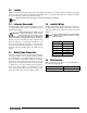
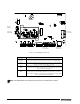
Figure 2-3. Counterpart CPU Board
If the RESET button on the CPU board is pressed, the scale will perform a reboot.
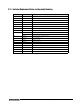
Jumper Description
JP1/JP2
JP3/JP4
Jump excitation to sense. If using a 4-wire load cell cable, leave JP1 and JP2
on. If using a 6-wire load cell cable, take JP1 and JP2 off. Default is ON.
JP5/JP6 Used when upgrading firmware. The jumpers should be on when upgrading
firmware and off when the update is complete.
PC 1
JMP2
Power control. If the jumper is set to SW, the POWER key can be used to turn
the unit on/off. If set to ON, the unit will power on when plugged in and can only
be powered off by unplugging.
AUDIT
JMP1
If set to Audit ON, calibration and configuration can be accessed through the
front keypad. If set to Audit OFF, calibration and configuration can only be
accessed by removing the screws from the unit and pressing the Setup switch
with a screwdriver. Default is Audit ON.
Table 2-5. Jumper Descriptions
LED
LED
JP1 JP2
JP3 JP4
JP5 JP6
PC1 Jumper
Power
Supply
Display
Backlight
Ethernet
Connector
Display
connector
RS-232
Connectors
Note