Counterpart ® Counting Scale Indicator Version 1.
Contents 1.0 Introduction.................................................................................................................................. 2 1.1 Standard Features . . . . . . . . . . . . . . . . . . . . . . . . . . . . . . . . . . . . . . . . . . . . . . . . . . . . . . . . . . . . . . . 2 1.2 Capacities and Resolutions . . . . . . . . . . . . . . . . . . . . . . . . . . . . . . . . . . . . . . . . . . . . . . . . . . . . . . . . 2 1.3 Modes of Operation . . . . . . . . . . . . . . . . . .
.1 4.2 4.3 4.4 Front Panel Calibration. . . . . . . . . . . . . . . . . . . . . . . . . . . . . . . . . . . . . . . . . . . . . . . . . . . . . . . . . . . EDP Command Calibration . . . . . . . . . . . . . . . . . . . . . . . . . . . . . . . . . . . . . . . . . . . . . . . . . . . . . . . Revolution® Calibration . . . . . . . . . . . . . . . . . . . . . . . . . . . . . . . . . . . . . . . . . . . . . . . . . . . . . . . . . . More About Calibration . . . . . . . . . . . . . . . . . . . . . . . . . . . . .
9.5 Custom Stream Formatting . . . . . . . . . . . . . . . . . . . . . . . . . . . . . . . . . . . . . . . . . . . . . . . . . . . . . . . 68 9.6 Digital Filtering . . . . . . . . . . . . . . . . . . . . . . . . . . . . . . . . . . . . . . . . . . . . . . . . . . . . . . . . . . . . . . . . . 71 9.6.1 9.6.2 9.6.3 9.6.4 DIGFLx Parameters . . . . . . . . . . . . . . . . . . . . . . . . . . . . . . . . . . . . . . . . . . . . . . . . . . . . . . . . . . . . . . . DFSENS and DFTHRH Parameters . . . . . . . . .
iv Counterpart User Manual
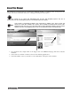
About This Manual This manual is provided for the use of trained and qualified installers of counting scales, and represents the correct, safe and recommended methods for setting up and using the Counterpart®. This manual can be viewed and downloaded from the Rice Lake Weighing Systems web site at www.ricelake.com. Rice Lake Weighing Systems is an ISO 9001 registered company. Note Some features of Counterpart included in this manual will be available soon. Those sections and features are noted.
1.0 Introduction The Counterpart offers practical solutions for a full range of precision counting applications. A bright LCD display enables operators to easily view quantities and alphanumeric text messaging displays part numbers to verify descriptions and correct part called from memory. One hundred and fifty (150) item memory and two RS-232 ports and Ethernet enable the Counterpart to provide real-time data collection and position it for the future growth of your business.
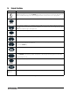
1.4 Keypad Functions Key Function Turns the Counterpart unit on/off. NOTE: If the PC1 jumper is set to SW, the POWER button must be used to turn the unit on and off. If the PC jumper is set to ON, the unit will automatically power on when it’s plugged in and the only way to turn it off is to unplug power. POWER Enters Menu mode, allowing configuration if the Audit jumper is in the “ON” position. Also used as an “escape” key in Menu mode.
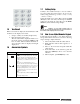
1.7 Softkey Setup Softkeys offer additional ways to access features associated with the Counterpart . To access the softkey setup parameter, go to Menu -> Setup -> Config -> Feature -> Softkeys. Select information for each softkey and press TARE (Enter) key after each entry and then press SaveExit softkey. To exit back out of the unit, press the MENU SETUP key twice without saving changes. Note Figure 1-1. Numeric Keypad 1.
1.9 Indicator Operations Basic Counterpart operations are summarized below. Toggle Gross/Net Press the GROSS/NET key to switch the display mode from gross to net or from net to gross. If a tare value has been entered or acquired, the net value is the gross weight minus the tare. If no tare has been entered or acquired, the display remains in gross mode. Gross mode and Net mode is indicated by the annunicator on the display. Set Date and Time 1. If the softkey is enabled, push the softkey.
2.0 Installation Counterpart is available in different configurations from just the indicator display to the display and counting scale combined together as a unit. This section contains instructions on unpacking and assembly, leveling, making power connections, load cell wiring, wiring standard serial port, optional network communications, wiring optional digital outputs, optional backup battery operation, and power-up sequence. Assembly drawings and replacement parts lists are also included.
2.2 Leveling Select a location for the Counterpart that is reasonably level and free of vibrations and air currents. Adjust the four corner feet on the scale base and refer to the bubble level on the inside frame. The base should not rock and the feet should have solid contact with the surface. Note 2.3 Ensure the nut on each foot’s bolt is secured flush against the scale base.
2.7 Cable Grounding Except for the power cord, all cables should be grounded against the scale enclosure. Do the following to ground shielded cables. • Use the lockwashers, clamps, and kep nuts provided in the parts kit to install grounding clamps on the enclosure studs. Install grounding clamps that will be used; do not tighten nuts. • Route cables and grounding clamps to determine cable lengths required to reach cable connectors.
2.7.3 2.10 Battery Replacement Network Connection to Counterpart Counterpart has an onboard Ethernet connection. It’s wireless connectivity is made possible with the optional Lantronix WiPort wireless networking device (PN 108671). Refer to the WLAN installation instructions (PN 108680) included with the option card for installing and configuration instructions.
PC1 Jumper Power Supply Display connector Display Backlight LED JP1 JP2 LED JP3 JP4 JP5 JP6 RS-232 Connectors Ethernet Connector Figure 2-3. Counterpart CPU Board Jumper Description JP1/JP2 JP3/JP4 Jump excitation to sense. If using a 4-wire load cell cable, leave JP1 and JP2 on. If using a 6-wire load cell cable, take JP1 and JP2 off. Default is ON. JP5/JP6 Used when upgrading firmware. The jumpers should be on when upgrading firmware and off when the update is complete.
2.
Figure 2-5.
Figure 2-6.
Figure 2-7. Counterpart Dimensions Figure 2-8.
3.0 Configuration 3.1 Front Panel Configuration To set up and configure the Counterpart counting Scale, you will use the MENU key on the front panel. The indicator is defaulted at the factory with the audit trail jumper (JMP1) in the ON position, allowing configuration access by pressing the Menu key. Pressing the MENU key will take you to the Audit menu selection. Use the SAMPLE ( ) and PRINT ( ) navigation keys to move to other menu selections.
Various keys are used as directional keys to navigate through the menus (see Figure 3-2). The SAMPLE ( ) and PRINT ( ) keys scroll left and right (horizontally) on the same menu level; ZERO ( ) and GROSS/NET ( ) move up and down (vertically) to different menu levels. Each of these keys has a directional symbol indicating its menu navigation function. The TARE (ENTER) key has the same function as GROSS/NET ( ) when navigating the menu-either will move down to access sub-categories of a main menu item.
3.4 Audit Menu The audit menu accesses audit trail support. It provides tracking information for configuration and calibration events. To prevent potential misuse, all configuration and calibration changes are counted as change events. Audit information can be printed by pressing the PRINT key while displaying the audit trail items beneath the AUDIT menu. ID AUDIT XXXXXXX CALIBR CALIB LRV SETUP TEST DISPLAY CFG Figure 3-4.
3.5 Menu Structures and Parameter Descriptions The Counterpart scale can be configured using a series of menus accessed through the scale front panel when the scale is in setup mode. Figure 3-5 and Table 3-3 summarizes the functions of each of the top level menus. ID AUDIT CALIBR SETUP TEST DISPLAY CONFIG SCALES FEATURE SERIAL ETHERNET PFORMT DIGIO VERS Figure 3-5.
Scale Parameter Levels ID Level 1 AUDIT XXXXXXX CALIBR SETUP TEST DISPLAY CONFIG Level 2 SCALES Level 3 Level 4 FEATUR SCALE 1 SERIAL SCALE 2 ETHERNET SCALE 3 GRADS CALIBR PFORMT DIGIO VERS Go to Scale 3 Submenu FORMAT MOTBAND OVRLOAD 1.900000 1 FS+2% 10 number number FS+1D number ZTRKBND ZRANGE 10000 0.000000 number number SSTIME FS+9D FS WZERO Previous A/D raw counts are shown Press Calibrate softkey to calibrate zero.
SETUP Menu Parameter Choices Description Level 3 submenu SCALES 1 AND 2 Allows configuration and calibration of each scale Level 4 submenus GRADS 10000 1–100000 Specifies the number of full scale graduations. The value entered must be in the range 1–100000 and should be consistent with legal requirements and environmental limits on system resolution. To calculate GRADS, use the formula: GRADS = Capacity / Display Divisions. Display divisions are specified under the FORMAT submenu.
SETUP Menu Parameter Choices Description DFSENS 4OUT 2OUT 8OUT 16OUT 32OUT 64OUT 128OUT Digital filter cutout sensitivity. Specifies the number of consecutive readings that must fall outside the filter threshold (DFTHRH parameter) before digital filtering is suspended. DFTHRH NONE 2D 5D 10D 20D 50D 100D 200D 250D Digital filter cutout threshold. Specifies the filter threshold, in display divisions.
SETUP Menu Parameter Choices Description Level 5 submenus - Format PRIMRY UNITS DECPNT DSPDIV Allows you to set the primary units, decimal point format, and display divisions. SEC KG G LB OZ OFF Allows you to set the secondary units. Decimal point format and display divisions are selected automatically. Values are kg=kilogram (default); g=gram; lb=pound; oz=ounce; and off. OFF KG G LB OZ Allows you to set the tertiary units.
3.6.2 SCALE 3 Submenu Scale Parameter Levels ID Level 1 AUDIT XXXXXXX CALIBR SETUP TEST DISPLAY CONFIG Level 2 SCALES FEATUR ETHERNET Level 3 SCALE 1 SCALE 2 SCALE 3 SERIAL PFORMT VERS ACCUM FORMAT PRIMRY DIGI/O SEC TER OFF ON **Scale 3 sub-menu appears only when serial port 1 is set to SCALE or IND. KG OFF G KG LB OZ * LB/OZ OFF G LB OZ UNITS DECPNT DSPDIV LB 8888800 1D OZ 8888880 2D KG G LB/OZ * 8888888 5D OFF 88.88888 8.888888 888.8888 8888.888 88888.
3.6.3 FEATUR Submenu Scale Parameter Levels Level 1 ID AUDIT XXXXXXX CALIBR SETUP TEST DISPLAY CONFIG Level 2 SCALES Level 3 SAMPLQTY NEGCOUNT SERIAL FEATURE ETHERNET COUNT INSFSMPL LOTUPDT REGION UID CONSC# 1 CURVAL VERS RESVAL 0 NEWITEM ON 10 0.1% OFF ON 25 0.2% ON OFF 50 0.
FEATUR Menu Parameter Choices Description Level 3 submenus - Feature COUNT NEGCOUNT SAMPLEQTY INSFSMPL LOTUPDT SCLCHG NEWITEM DISPACC Selects the counting mode (enables/disables negative checkweighing; turns data parameters on/off. See Level 3 submenus. UNITWTUPDATE UTWTBASE REGION REGULA REGWRD DECFMT TIME DATE Selects regional settings. See Level 3 submenus. UID 1 Sets the unit ID, a string of up to 6 ASCII characters, which can be set via serial port or keypad.
FEATUR Menu Parameter Choices Description RECALL ON OFF ON allows the Tare, Zero, and Units values to be maintained across a power cycle. Over/ Under/Target/ID values are also maintained. OFF clears the values on a power cycle. Zero is reset to calibrated zero and Units are reset to Primary. Over/Under/Target/ID values are reset as well. DISPLAY CONTRAST BRIGHT IMAGE Adjusts Counterpart display viewing.
FEATUR Menu Parameter Choices Description DISPMODE Count Weigh Unit Weight Display mode. This chooses the value to be displayed as large in viewing window. Level 4 submenus - under the Level 3 Region Feature REGULA NTEP CANADA INDUST NONE OIML Regulatory mode. Specifies the regulatory agency having jurisdiction over the scale site. Note • • • • • The value specified for REGULA affects the function of the front panel TARE and ZERO keys.
FEATUR Menu Parameter Choices Description SK1-12 BLANK TIMEDATE CLR TAR DSPTAR DSP ACC SCL SEL CODE LOT PRINT PLT SWAP DSP IN OUT CLR CN TOTAL + TOTAL CLR TTL Labels softkeys for access to function stated. Level 4 submenus - under the Level 3 Keylock Feature MENU UNLOCK LOCK ZERO UNLOCK LOCK GRS NET UNLOCK LOCK UNITS UNLOCK LOCK PRINT UNLOCK LOCK TARE UNLOCK LOCK NUMBER UNLOCK LOCK SAMPLE UNLOCK LOCK UNIT WT UNLOCK LOCK Allows the user to lock or unlock keys of the Counterpart.
FEATUR Menu Parameter Choices Description DFORMT MMDDY4 DDMMY4 Y4MMDD Y4DDMM MMDDY2 DDMMY2 Y2MMDD Y2DDMM Sets the date format. Y4 will use a four-digit year value, such as 2011, while Y2 will use a two-digit value, such as 11. D SEP SLASH DASH SEMI Sets the date separator as a slash, dash, or semicolon. Level 5 submenus - Under the Level 4 TIME Feature TFORMT 12 HOUR 24 HOUR Sets the time format. T SEP COLON COMMA Sets the time separator as a colon or a comma. Table 3-7.
FEATUR Menu, REGULA / INDUST Submenu Parameter Choices Description LEVEL 6, REGULA / INDUST submenu KTARE YES NO Always allow keyed tare. MTARE REPLAC REMOVE NOTHIN Multiple tare action. NTARE NO YES Allow negative or zero tare. CTARE YES NO Allow CLEAR key to clear tare/accumulator. PRTMOT NO YES Allow print while in motion. PRTPT NO YES Add PT to keyed tare print. OVRBAS CALIB SCALE Zero base for overload calculation.
3.6.5 Serial, PFORMT, DIG I/O, VERS Submenus Scale Parameter Levels Level 1 ID AUDIT XXXXXXX CALIBR SETUP TEST DISPLAY CONFIG Level 2 SCALES FEATUR See SCALE Submenu See FEATUR Submenu SERIAL ETHERNET PFORMT DIGI/O VERS SOFTWR REG V 1.03 LR, V.1.
SETUP Menu Parameter Choices Description Level 2 submenus SCALE See Section 3.6.1 on page 18 Configure scale settings. See the level 3 submenus of Table 3-5 on page 20 for parameter descriptions. FEATURE See Section 3.6.3 on page 24 Set counting options, region settings, view Unit ID, and set consecutive numbering. See level 3 submenus of Table 3-7 on page 25 for parameter descriptions. SERIAL PORT 1 PORT 2 PORT 3 (Option Card) Configure communications ports.
SETUP Menu Parameter Choices Description Level 3 submenus - Under the Level 2 Version Feature SOFTWR V1.XX Displays the software version REG LR, V 1.
SETUP Menu Parameter Choices Description IND SCALE BAUD BITS STOP BITS TERMIN EOLDY SFMT Sets up the transmission information for the industrial scale parameter. Table 3-9.
3.7 Calibration Menu See Section 4.0 on page 39 for calibration procedures. The Calibration menu can be protected by assigning a password in the Feature menu. Note The Counterpart requires the WZERO and WSPAN points to be calibrated. The linearity points are optional, but must NOT duplicate zero or span. During calibration, the TARE key acts as a data entry confirmation key. It also acts as an EXECUTE key, and accepts the value if calibration was successful.
3.8 Test Menu ID AUDIT XXXXXXX A/D CALIBR SETUP DIG I/O TEST DISPLAY COMM WARNING... DISCONNECT DIGITAL I/O BEFORE RUNNING TEST PORT1 PORT2 PASS or FAIL PASS or FAIL RAM KEYPAD PASS or FAIL TEST LOOP DIO 1 DIO 2 DIO 3 DIO 4 PASS or FAIL STATUS STATUS STATUS STATUS COMING SOON AD1 AD2 RAW ZERO SPAN mV EXCVDC VAL VAL VAL VAL VAL VAL VAL Figure 3-12.
TEST Menu Parameter Choices Description LOOP TEST Performs a loop test on dig I/O cards. DIO 1 DIO 2 DIO 3 DIO 4 STATUS Displays the status of each individual digital I/O port. If set as input, the display shows input stats IN HI or IN LO. If set as output, pressing Enter toggles the output between HI and LO. OUT HI or OUT LO. OUT LO is active. PORT1 PORT2 TEST Performs a loopback test on serial port 1 or 2. Connect jumper TX and RX together on port 1 or port 2 before testing. Table 3-11.
3.10 ID Menu The ID menu displays parameters for registers from 1 to 150. Sub-parameters are shown below. ID AUDIT XXXXXXX CALIBR SETUP TEST REG 2 REG 150 SAME AS REG 1 SAME AS REG 1 REG 1 QUANTITY CODE DESC VALUE VALUE VALUE DISPLAY PART NUM LOT VALUE VALUE UNIT WT VALUE TARE VALUE UNITS LOCATION LB VALUE OZ KG G OFF Figure 3-14.
4.0 Calibration The Counterpart can be calibrated using the front panel, EDP commands, or Revolution®. Note Calibration can be performed in two places within the menu: the CALIBR menu shown in Figure 4-1 and the SCALE submenu shown in Figure 3-6 on Page 18. The CALIBR menu shown in Figure 4-1 is a “quick access” calibration; for more in-depth scale setup and calibration, use the menus found under SETUP»CONFIG»SCALE (see Figure 3-6 on Page 18).
Five-point linearization - COMING SOON Rezero - COMING SOON 4.2 EDP Command Calibration To calibrate the indicator using EDP commands, the indicator EDP port must be connected to a terminal or personal computer. See Section 2.7.1 on page 8 for EDP port pin assignments. Once the indicator is connected to the sending device, do the following: 1. Place the indicator in config mode (display must read SCALE - see Figure 3-6 on page 19) and remove all weight from the scale platform.
4.4 More About Calibration The following topics provide additional information about compensating for environmental factors (Section 4.4.1) and diagnostic information for determining expected zero and span coefficients. 4.4.1 Adjusting Final Calibration Calibration may be affected by environmental factors including wind, vibration, and angular loading. For example, if the scale is calibrated with 1000 lb, a strain test may determine that at 2000 lb the calibration is 3 lb high.
5.0 Scale Operations The following paragraphs contain detailed operator instructions for Counterpart. Included are instructions to enter tare weights, toggle between net and gross weight, enter unit weights, perform inventory accumulation and reduction, and toggle between scales. All operator instructions are conducted with the scale in the operation mode that is the weighing or normal mode.
5.3 Toggling Between Gross and Net To toggle between net and gross weight, a tare value must be entered into the scale. Follow Section 5.2 to enter a tare value. After a tare value is entered into the scale, items placed on the scale will cause the net annunciator to illuminate and allow toggling between net weight and gross weight. An example of toggling between net weight and gross weight is shown below: 1. Place 0.5 lb weight on the scale and then press TARE once. The weight display should show 0.
5.4.1 Unit Weight Operation by Sampling Unit weight operation by sampling is accomplished by placing a 10 piece sample on the scale and then pressing the SAMPLE key. The scale calculates a unit weight based on the weight of the sample. The following paragraphs detail the procedure with UNIT WEIGHT either set at on or off. Default settings are placed at 10 pieces but if you want to key in a larger sample, key in the quantity and press TARE(Enter).
Counting Out of a Full Container - See Total Amount Remaining in the Container To carry out this operation you must know the tare weight ahead of time. 1. Place the full container on the scale. Press the TARE key. 2. Remove a 10 piece sample to the container and press the SAMPLE key. After the unit weight has been calculated, return the 10 piece sample to the container. 3. If you want to see how many are still in the bin you first have to know the tare weight of the bin or container.
4. When you have reached the REG number you want to set, press to select that register number. 5. Press and enter the CODE value - either the numeric or alpha-numeric is acceptable. Thirty two characters can be entered and 25 characters maximum for bar code entries. This is the code that will be used to recall the ID. 6. When the desired value is entered, press TARE(Enter). 7. Enter in the information for description, part number, lot number, unit weight, tare, etc. with all entries being optional. 8.
5.5.3 Adding an ID From Count Mode 1. 2. 3. 4. 5.5.4 Press the CODE softkey. Add in the ID number. If the ID number is not already in the database, Counterpart prompts, Not Found, Save as New ID? Select Yes or No. By selecting Yes, Counterpart will store that ID code into the first open register. By selecting No, you will go back to the Counting mode screen. Adding an ID Through Revolution To add an ID using Revolution, you must have Revolution installed on your computer. Visit www.ricelake.
5.5.5 WeighVault WeighVault is a PC program which allows Counterpart users to add, edit, and access IDs over a network connection. WeighVault surpasses the Counterpart's 150 ID limitation and eliminates front-panel entry of ID parameters. It also collects data as transactions occur, and provides detailed transaction and productivity reports which can be exported to Excel, Word, or PDF.
5.6 Totalization Counts Counterpart has a totalization function that allows you to totalize the quantity of several weighings together. This is especially helpful if putting together parts kits Use the following steps to totalize parts. 1. Conduct a sampling process to determine the unit weight of the pieces. Or key in a known unit weight or recall an ID. 2. Enter a known tare weight or place an empty container on the scale to perform tare function.
5.8 Connecting a Barcode Scanner The Counterpart will accept a barcode scanner connected to the unit. In order to use a scanner, you must set the specifications of the Counterpart scale to recognize the scanner to the appropriate port and in some cases, do the setup on the scanner required by the scanner manufacturer. The scanner allows non-contact, instantaneous, and accurate input of unit weight, tare weight, and ID code.
6.0 Serial Commands The Counterpart can be controlled by a PC or remote keyboard connected to an indicator serial port. Control is provided by a set of serial commands that can simulate front panel key press functions, display and change setup parameters, and perform reporting f u n c t i o n s . T h i s p r o v i d e s t he a b i l i t y t o p r i n t configuration data or to save to your hard drive. 6.
6.1.2 Keypad Lock The user has the ability to lock or unlock the keypad. The commands are listed in Table 6-2. Command Parameter KEYLCK.NUMBER Keys can be locked or unlocked. Default for all: Unlock KEYLCK.PRINT KEYLCK.TARE KEYLCK.ZERO KEYLCK.SAMPLE KEYLCK.GROSSNET KEYLCK.UNITWT Table 6-2. Keypad Lock Commands 6.1.3 ID Commands Up to 150 codes can be entered under ID commands. Command Function ID.CODE#n (#n = ID Code number referenced) ID.DESC#n (#n = item description) ID.
6.1.5 Reporting Commands 6.1.6 Reporting commands send specific information to the serial port. The commands listed in Table 6-5 can be used in all modes. Command Function Clear and Reset Commands The following commands can be used to clear and reset the Counterpart: RS : Reset system. Resets the indicator without resetting the configuration. RESETCONFIGURATION: Restores all configuration parameters to their default values (menu mode only).
Command Description Values SC.GRADS#n Graduations 1–100000 SC.ZTRKBND#n Zero track band 0, 0–100 SC.ZRANGE#n Zero range 1.900000, 0–100 SC.MOTBAND#n Motion band 1, 0–100 SC.SSTIME#n Standstill time 1–65535 SC.OVRLOAD#n Overload FS+2%, FS+1D, FS+9D, FS SC.DIGFLTR1#n SC.DIGFLTR2#n SC.DIGFLTR3#n Digital filtering 1, 2, 4, 8, 16, 32, 64, 128, 256 SC.DFSENS#n Digital filter cutout sensitivity 2OUT, 4OUT, 8OUT, 16OUT, 32OUT, 64OUT, 128OUT SC.
Command Description Values EDP.ECHO#p Port echo ON, OFF EDP.EOLDLY#p Port end-of-line delay 0–255 (0.1-second intervals) EDP.HEADERS#p Port header ON, OFF EDP.INPUT#p Port input CMD, SCANNER, SCALE, IND SC EDP.PORT Port reporting command. It responds to the port you are connected to. EDP.RESPONSE#p Port response ON, OFF EDP.SFMT#p Port custom stream format 0-200 characters EDP.SOURCE#p Port source 1, 2, 3 EDP.STREAM#p Port stream OFF, LFT, INDUST EDP.
Command Description Values REG.BASE Zero base for overload calculation CALIB, SCALE REG.PRTMOT Allow print while in motion NO, YES REG.PRINTPT Add PT to keyed tare print NO, YES REG.SNPSHOT Display or Scale weight source DISPLAY, SCALE SD Set date MMDDYY, DDMMYY, YYMMDD, or YYDDMM. Enter six-digit date using the year-month-day order specified for the DATEFMT parameter, using only the last two digits of the year.
6.1.8 Normal Mode Commands The normal mode print commands (see Table 6-12) transmit data to the serial port on demand in either setup or normal mode. Command Description Values CONSNUM#n Set consecutive number 0–9 999 999 UID#n Set unit ID nnnnnnn SD#n Set date MMDDYY, DDMMYY, YYMMDD, or YYDDMM. Enter six-digit date using the year-month-day order specified for the DATEFMT parameter, using only the last two digits of the year.
7.0 Print Formatting The Counterpart provides eight print formats, GFMT, NFMT, TOTALFMT, PALFMT, CFMT, ACCFMT, HDRFMT1 and HDRFMT2. These determine the format of the printed output when the PRINT key is pressed or when a KPRINT EDP command is received. The HDRFMTs must be called from another format. Each print format can be customized to include up to 500 characters of information, such as company name and address, on printed tickets.
Command Supported Ticket Formats Description Gross weight in displayed units Net weight in displayed units Tare weight in displayed units.
Command Description Supported Ticket Formats Gross, net, and tare weights are 8 digits in length, including sign and decimal point, followed by a space and a one- to five-digit units identifier. Total field length with units identifier is 10-14 characters. Depending on what units are configured, the units identifier will be lb, oz, g, or kg.
The default Counterpart print formats are shown in Table 7-2 and Table 7-3: Format Default Format String Sample Output H1 Company Name Street Address City, ST ZIP Company Name, Street Address, City, ST ZIP H2 Company Name Street Address City, ST ZIP Company Name, Street Address, City, ST ZIP Table 7-3. H1, H2 Formats 7.
ID AUDIT XXXXXXX CALIBR SETUP TEST ACCUM DISPLAY CONFIG SCALES FEATURE GFMT NFMT SERIAL CFMT ETHERNET PALFMT PFORMT ACCFMT TOTALFMT DIGIO H1 VERS VERS H2 Same as GFMT Scroll left in formatting string Display first 6 characters of format Press INSERT to enter a space before the active character Scroll right in formatting string Press to cycle the active character to the previous character Press to cycle the active character to the next character Press CLR to delete the character
7.2.4 Print Label Examples Listed below are print formatting examples that appear with the various formats. Count Format Figure 7-3. Count Format Label Example Pallet Label Format Figure 7-4. Pallet Format Label Example Gross Label Format Figure 7-5.
Total Label Format Figure 7-6. Total Format Label Example Gross/Tare/Net Label Format Figure 7-7.
8.0 WLAN Installation Instructions Note Before installing this option, you must contact your IT administrator to obtain network communication protocol codes and have a RS-232 communications cable or regular comm port cable available to run between your PC and the indicator while installing and setting up the wireless network.
9.0 9.1 Appendix Error Messages If an error code appears on the display, use the information in Table 9-1 as a troubleshooting guide. If you cannot clear the error, call RLWS Service for assistance. Error Display - - - - - - Description Over range Under range - - - - - - - - - - - - - - - - A/D out of range Solution • Check load cell wiring, including sense jumpers. • Check configuration, including number of grads, channel selection, display divisions.
XE Error Code Description XEH Hex Value 1 VIRGERR 0x00000001 2 PARMCHKERR 0x00000002 4 LOADCHKERR 0x00000004 8 PRINTCHKERR 0x00000008 16 ENVRAMERR 0x00000010 32 ENVCRCERR 0x00000020 64 BATTERYERR 0x00000040 32768 GRAVERR 0x00008000 65536 ADPHYSICALERR 0x00010000 131072 TAREERR 0x00020000 262144 EACCOVER 0x00040000 524288 STRINGERR 0x00080000 1048576 RESERVED_PF 0x00100000 2097152 RTCERR 0x00200000 4194304 MISSINGHWERR 0x00400000 8388608 CFGCONFLICTERR 0x0080
9.3 Continuous Output (Stream) Format Figure 9-1 shows the continuous output format sent to a Counterpart port when that port’s TRIGGE parameter (SERIAL menu) is set to STREAM.
Format Identifier Defined By Description STR.GROSS STR.NET STR.TARE Mode. Specifies gross, net, or tare weight for the current or specified weight on the source scale. STR.MOTION STR.RANGE STR.OK STR.INVALID Status for the source scale. Default values and meanings for each status: STR.MOTIONMIn motion STR.RANGEOOut of range STR.OKOK STR.INVALIDIInvalid — Status of over/under/accept. O=Over, U=Under, A=Accept. See descriptions below Bit fields.
Format Identifier Defined By Description B17 Configuration =000 if current DECPNT=8888800 =001 if current DECPNT=8888880 =010 if current DECPNT=8888888 =011 if current DECPNT=888888.8 =100 if current DECPNT=88888.88 =101 if current DECPNT=8888.888 =110 if current DECPNT=888.8888 =111 if current DECPNT=88.88888 B18 Configuration =000 if primary DECPNT=8888800 =001 if primary DECPNT=8888880 =010 if primary DECPNT=8888888 =011 if primary DECPNT=888888.8 =100 if primary DECPNT=88888.
9.6 Digital Filtering The Counterpart uses averaged digital filtering to reduce the effect of vibration on weight readings. Adjustable threshold and sensitivity functions allow quick settling by suspending filter averaging, allowing the weight reading to jump to the new value. Figure 9-2 shows the digital filter parameters on the CONFIG menu.
9.6.3 Setting the Digital Filter Parameters Fine-tuning the digital filter parameters greatly improves indicator performance in heavy-vibration environments. Use the following procedure to determine vibration effects on the scale and optimize the digital filtering configuration. 1. In menu mode, set all three digital filters (DFLTR1, DFLTRL2, DFLTR3) to 1. Set DFTHRH to NONE. Return indicator to normal mode. 2.
9.7 Serial Scale Interface Serial port 1 can be configured for serial scale input. The serial scale function allows other scale indicators to send gross, or net weight data to Counterpart. Once the serial port has been configured to accept scale data, the data format can be customized to match the data stream sent by that indicator. See Figure 3-9 on page 28 for information setting up To set up and configure a serial scale, do the following: 1.
9.8 Regulatory Mode Functions The function of the front panel TARE and ZERO keys depends on the value specified for the REGULAT parameter on the FEATURE menu. Table 9-4 describes the function of these keys for the NTEP, CANADA, OIML, and NONE regulatory modes. TARE and ZERO key functions are configurable when the REGULAT mode is set to INDUST (see Table 9-5 on page 74).
9.9 Updating Firmware To update firmware of the Counterpart, you must have Revolution installed and a .hex file on your computer. Visit www.ricelake.com to download this free configuration software and the latest .hex file. Note If the hex file is the same version as is currently in the indicator, the firmware update will not reset the configuration. This is helpful if the firmware becomes corrupt and you want to reload the same firmware.
Figure 9-5. Rice Lake Updater Screen 8. Click the Program button. The update will take several moments. 9. When complete, remove the jumpers shown in Figure 4 on page 75 and press the Power button to power up the indicator. 9.10 Specifications Part # Description Weighing Resolution Platter Dimensions Single Channel 118788 CP Indicator Console only 120736 CP-5 5 lb x 0.0005 lb (2 kg x 0.0002 kg) 9 in x 12 in 120737 CP-10 10 lb x 0.001 lb (5 kg x 0.
9.11 Specifications CERTIFICATIONS AND APPROVALS Counterpart Indicator NTEP (Pending) - $ 0 / ' & t / " 5 * / " 0 3 ) 5 4 6 3 ( & 4 t .3 Two-year limited warranty $ & & / 0-4.5 mV/V ANALOG SPECIFICATIONS: APPROVALS: Pending WARRANTY: * & 0 / 8 POWER: Power source: Input: 100-240VAC, 47-63 Hz, 5 watts, US power cord Output: 9VDC or 12VDC 1.25 max EXCITATION VOLTAGE: 5VDC ANALOG SIGNAL INPUT RANGE: " 4 " / % .
Counterpart Limited Warranty Rice Lake Weighing Systems (RLWS) warrants that all RLWS equipment and systems properly installed by a Distributor or Original Equipment Manufacturer (OEM) will operate per written specifications as confirmed by the Distributor/OEM and accepted by RLWS. All systems and components are warranted against defects in materials and workmanship for two years. RLWS warrants that the equipment sold hereunder will conform to the current written specifications authorized by RLWS.
For More Information Literature • • • Counterpart Sales Literature, PN 125545 Counterpart CD with WeighVault, PN 125546 Weighvault manual for Counterpart, PN 125561 Web Site • Frequently Asked Questions (FAQs) at http://www.ricelake.com/faqs.aspx Contact Information Hours of Operation Fax Knowledgeable customer service representatives are available 6:30 a.m. - 6:30 p.m. Monday through Friday and 8 a.m. to 12 noon on Saturday.
PN 118677 06/11