
User Manual Rev. D - Version 2.4 Instruction Manual

Configuration 29
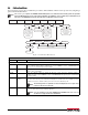
Parameter Choices Description
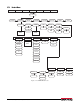
Scales 1 and 2 Allows configuration and calibration of each scale.
Scale 3 Allows configuration and calibration of scale 3.
Scales sub-menu
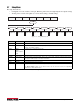
GRADS 10000
1–100000
Specifies the number of full scale graduations.
The value entered must be in th
e range 1–100000 and should be consistent with legal
requirements and environmental limits on system resolution.
To calculate GRADS, use the formula: GRADS = Capacity / Display Divisions.
Display divisions are specified under the FORMAT sub-menu.
FORMAT PRIMRY
SEC
TER
Select your primary, secondary, and tertiary uni
ts of measure. Sub-choices include lb, kg, oz,
and g. See Format menu, Figure 3-10.
ACCUM OFF
ON
Scale 3 only.
ZTRKBND 0.000000
number
Automatically zeros the scale when within the range specified, as long as the input is within
the ZRANGE and scale is at standstill. Specify the zero tracking band in ± display divisions.
Maximum legal value varies depending on local regulations.
Note
For scales using linear calibration, do not set the zero tracking band to a
value greater than that specified for the first linearization point.
ZRANGE 1.900000
number
Selects the range within which the scale can be z
eroed. The 1.900000 default value is ± 1.9%
around the calibrated zero point, for a total range of 3.8%. Indicator must be at standstill to
zero the scale. Use the default value for legal-for-trade applications.
MOTBAND 1
number
Sets the level, in display divisions, at which scale motion is detected. If motion is not detected
for 1 second or more, the standstill symbol lights. Some operations, including print, tare, and
zero, require the scale to be at standstill. Maximum legal value varies depending on local
regulations.
If this parameter is set to 0 the standstill ann
unciator does not light; operations normally
requiring standstill (zero, tare, print) are performed regardless of scale motion. If 0 is selected,
ZTRKBND must also be set to 0.
OVRLOAD FS+2%
FS+1D
FS+9D
FS
Overload. Determines the point at which the display blanks and an out-of-range error
message is displayed. Maximum legal value varies depending on local regulations.
SSTIME 10
number
Specifies the length of time the scale must be ou
t of motion, in 0.1-second intervals, before
the scale is considered to be at standstill. Values greater than 10 are not recommended.
DFLTR 1-3 4
8
16
32
64
128
256
1
2
Selects the digital filtering rate used to reduce the ef
fects of mechanical vibration from the
immediate area of the scale. The overall filtering effect can be expressed by adding the values
assigned to the three filter stages:
DFLTR1 + DFLTR2 + DFLTR3
See Section 9.6 on page 94 for information on digital filt
ering.
Choices indicate the number of AD conversions per update tha
t are averaged to obtain the
displayed reading. A higher number gives a more accurate display by minimizing the effect of
a few noisy readings, but slows down the settling rate of the indicator.
DFSENS 4OUT
2OUT
8OUT
16OUT
32OUT
64OUT
128OUT
Digital filter cutout sensitivity. Specifies the
number of consecutive readings that must fall
outside the filter threshold (DFTHRH parameter) before digital filtering is suspended.
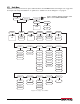
Table 3-7. Scales Menu Parameters