
User Manual Rev. D - Version 2.4 Instruction Manual

Installation 15
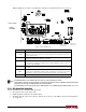
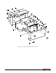
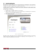
7. Run cable over to power plug J12 on the Counterpart CPU board.
Figure 2-13. Connect Power Plug onto J12 on CPU Board
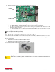
8. Unplug existing power off the CPU board and plug in battery plug J1 on battery CPU.
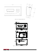
9. AC plugs into the back of the unit.
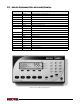
Red and green LEDs located on the battery CP
U board tell the user whether the battery is fully charged or not.
2.13 Installing Option Cards
Note
Disconnect power cord before installing option cards.
Ethernet port is not suitable for connection to circuits used out
side the building and is subject to lightning or
power faults.
Each option card is shipped with installation instructions specific to that card. For specific instructions on the
WLAN card, refer to Section 8.0 on page 88.
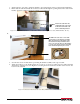
The general procedure for all option cards is:
1. Disconnect power cord from the scale.
2. Install the plastic standoffs in the standoff holes.
3. Carefully align the option card connector with th
e J14 connector on the CPU board.
4. Press down firmly to seat the option
card in the CPU board connector.
5. Make connections to the option ca
rd as required. Use cable ties to secure loose cables inside the enclosure.