Counterpart ® Counting Scale Indicator Version 2.
Contents 1.0 Introduction..................................................................................................................................... 2 1.1 Standard Features . . . . . . . . . . . . . . . . . . . . . . . . . . . . . . . . . . . . . . . . . . . . . . . . . . . . . . . . . . . . . . . . . 2 1.2 Capacities and Resolutions . . . . . . . . . . . . . . . . . . . . . . . . . . . . . . . . . . . . . . . . . . . . . . . . . . . . . . . . . . 2 1.3 Modes of Operation. . . . . . . . . . . . .
3.7.3 3.7.4 3.7.5 3.7.6 3.7.7 3.7.8 Serial Menu. . . . . . . . . . . . . . . . . . . . . . . . . . . . . . . . . . . . . . . . . . . . . . . . . . . . . . . . . . . . . . . . . . . . . . . Ethernet Menu . . . . . . . . . . . . . . . . . . . . . . . . . . . . . . . . . . . . . . . . . . . . . . . . . . . . . . . . . . . . . . . . . . . . Print Format Menu . . . . . . . . . . . . . . . . . . . . . . . . . . . . . . . . . . . . . . . . . . . . . . . . . . . . . . . . . . . . . . . . . Scale Setpoints Menu . .
7.0 Print Formatting ............................................................................................................................ 79 7.1 Print Formatting Commands . . . . . . . . . . . . . . . . . . . . . . . . . . . . . . . . . . . . . . . . . . . . . . . . . . . . . . . . 79 7.2 Customizing Print Formats. . . . . . . . . . . . . . . . . . . . . . . . . . . . . . . . . . . . . . . . . . . . . . . . . . . . . . . . . . 83 7.2.1 7.2.2 7.2.3 7.2.4 8.0 Using the EDP Port . . . . . . . . . .
iv Counterpart Counting Scale Indicator
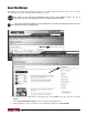
About This Manual This manual is for trained and qualified installers of counting scales and represents the correct, safe and recommended methods for setting up and using the Counterpart®. This manual can be viewed and downloaded from the Rice Lake Weighing Systems web site at www.ricelake.com. Rice Lake Weighing Systems is an ISO 9001 registered company. For the latest downloads available, sign up for email updates on the Rice Lake Weighing Systems web site at Note http://www.ricelake.com/software.aspx.
1.0 Introduction The Counterpart offers practical solutions for a full range of precision counting applications. A bright LCD display enables operators to easily view quantities, alphanumeric text messaging displays, part numbers to verify descriptions, and correct part called from memory. One hundred and fifty item memory and two RS-232 ports and Ethernet enable the Counterpart to provide real-time data collection and position it for the future growth of your business.
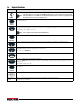
1.4 Keypad Functions Key Function Turns the Counterpart unit on/off. If the PC1 jumper is set to SW, the POWER button must be used to turn the unit on and off. Note If the PC jumper is set to ON, the unit will automatically power on when it’s plugged in and POWER the only way to turn it off is to unplug power. Enters Menu mode, allowing configuration if the Audit jumper is in the “ON” position. Also used as an escape key in Menu mode.
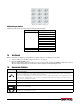
Figure 1-1. Numeric Keypad Additional Keypad Symbols Additional symbols can be accessed by pressing the following keys. Key Symbol 1 < > + * $ / % " 0 * . (period) space Table 1-3. Additional Keypad Symbols 1.5 Tare Recall When a stored tare is displayed, Net annunciators will be turned on. To display a stored tare, 1. Set up a softkey (see Softkey Setup in Section 1.7 on page 5). 2. Press the DISPLAY TARE softkey. The tare value will be displayed.
1.7 Softkey Setup Softkeys offer additional ways to access features associated with the Counterpart. To access the softkey setup parameter, go to Menu/Setup/Config/Feature/Softkeys. Select information for each softkey and press TARE (Enter) key after each entry and then press SaveExit softkey. To exit back out of the unit, press the MENU SETUP key twice without saving changes.
Set Date and Time 1. If the softkey is enabled, push the softkey. The current value is displayed. 2. To change, use the Up/Down arrows to highlight the value to change. 3. Press the TARE key to save and exit. Set Serial Scale (Scale 3) 1. Select Port 1 — Indust Scale. 2. Match the baud rates. Upon doing this it automatically becomes Scale 3. Setting up a Softkey To set up a softkey, use the following steps: 1. 2. 3. 4. 5. 6. 7. 8. 9. 10. 11. 12. 6 Press the MENU SETUP key.
2.0 Installation Counterpart is available in different configurations from just the indicator display to the display and counting scale combined together as a unit. This section contains instructions on unpacking and assembly, leveling, making power connections, load cell wiring, wiring standard serial port, optional network communications, wiring optional digital outputs, optional backup battery operation, and power-up sequence. Assembly drawings and replacement parts lists are also included.
2.2 Scale Base Assembly (if purchasing the scale base separate from indicator) Do not turn the scale upside down. Always work with the scale on its side. Damage to the load cell can Important occur if the scale is turned upside down. Set up the scale on a stable, level surface. 2.2.1 Locking and Unlocking - S-XL Scale Base The Counterpart S-XL scale base is delivered in a locked position to prevent damage to the load cells during shipment.
2.2.3 Leveling Select a location for the Counterpart that is reasonably level and free of vibrations and air currents. Adjust the four corner feet on the scale base and refer to the bubble level on the inside frame. The base should not rock and the feet should have solid contact with the surface. Note Ensure the nut on each foot’s bolt is secured flush against the scale base. To ensure greater scale stability, turn in all four adjustable legs before leveling. Turn out adjustable legs to level as needed.
5. Push the plastic bushing all the way into the enclosure to make a tight seal in the hole. Remove four screws (only one shown). Push bushing all the way to enclosure to seal. Figure 2-5. Use Plastic Bushings Bushings are not a “cord grip.” Bushings allow for free movement of cable while protecting them from the Note enclosure sides. 2.5 Making Power Connections The power source used for the Counterpart must be properly grounded to an acceptable earth ground and the outlet must be a grounded outlet.
2.6.1 Dual Channel Units (S-XD Base) For units that have dual channels, connect cable from the 14 pin connector to J1 and J2. If not using a dual base, remove the J2 connector as shown in Figure 2-8. Trim back the wires and tape. Shown connectors shipped from the factory. Remove connector off of J2 and tie off two wires. Figure 2-7. J2 Connector Location 2.6.2 Dual Channel – Remote Scale Setup For units that have dual channels and want to set up a scale remotely, use the following steps: 1.
2.8 Cable Grounding Except for the power cord, all cables should be grounded against the scale enclosure. Do the following to ground shielded cables. • Use the lockwashers, clamps, and kep nuts provided in the parts kit to install grounding clamps on the enclosure studs. Install grounding clamps that will be used; do not tighten nuts. • Route cables and grounding clamps to determine cable lengths required to reach cable connectors. Mark cables to remove insulation and shield as described below.
2.8.2 Digital I/O The Digital I/O can be configured as either digital inputs or digital outputs as determined by the Digital I/O menu (see Section 3.7.3 on page 42). The inputs are active (on) with low voltage (0 VDC) and can be driven by TTL or 5V logic without additional hardware. Use the Digital I/O menu (see Section 3.7.3 on page 42) to configure the digital inputs. LEDs on the CPU board light when digital inputs are active (see Figure 2-10).
2.11 CPU Board Battery Replacement Risk of explosion exists if battery is replaced with incorrect type. Dispose of batteries according to CAUTION manufacturer instructions. The lithium battery on the CPU board maintains the real-time clock and protects data stored in the system RAM when the indicator is not connected to AC power. Data protected by this battery includes time and date, IDs, buffered WeighVault transaction data and setpoint value data.
7. Run cable over to power plug J12 on the Counterpart CPU board. Figure 2-13. Connect Power Plug onto J12 on CPU Board 8. Unplug existing power off the CPU board and plug in battery plug J1 on battery CPU. 9. AC plugs into the back of the unit. Red and green LEDs located on the battery CPU board tell the user whether the battery is fully charged or not. 2.13 Installing Option Cards Disconnect power cord before installing option cards.
When installation is complete, reassemble the enclosure as described in Section 2.9 on page 13 ON +3.3v SW PC1 +5 R WD1 P U G N M C3 PWR Port 3 LED Power Supply Display Backlight LED LED JP1 JP2 JP3 JP4 JP5 JP6 RST ISP RS-232 Connectors Ethernet Connector Figure 2-14. CPU Board Jumper Description JP1/JP2 JP3/JP4 Jump excitation to sense. If using a 4-wire load cell cable (JP3 and JP4 for scale number 2), leave JP1 and JP2 on. If using a 6-wire load cell cable, take JP1 and JP2 off.
4. Press down firmly to seat the option card in the CPU board connector. D1 LED D6 LED D5 LED Figure 2-15. Installing the USB Option Card 5. Several signal LEDs are located on the USB option board as shown in Figure 2-15. • D5 — When flashing, it indicates that a keyboard is connected and has been detected. • D6 — Is lit continuously when the option board is waiting for a keyboard to be connected. It is off when a keyboard is connected.
1. Stand scale base on its side to attach the bracket to the scale using the screws provided in the bracket kit. 2. Ensure that the cable underneath the scale base is threaded through the opening between the scale and the bracket, otherwise it will not fit.(shown in Figures 2-18 and 2-19). Ensure the cable from the Note underside of the scale is run between bracket and scale prior to attaching bracket. Figure 2-17.
2.
Figure 2-22.
Figure 2-23. Counterpart Dimensions Figure 2-24.
3.0 Configuration The Counterpart scale can be configured using a series of menus accessed through the scale front panel when the scale is in setup mode. Figure 3-1 and Table 3-1 on page 22 summarizes the functions of each of the top level menus. Note To navigate through the menus, use the front panel keys and shown in Figure 3-2 on page 22. 3.1 Front Panel Configuration To set up and configure the Counterpart counting scale, select the MENU key on the front panel.
3.3 Revolution Configuration The Revolution configuration utility provides the preferred method for configuring the Counterpart indicator. Revolution runs on a personal computer to set configuration parameters for the indicator. When Revolution configuration is complete, configuration data is downloaded to the indicator. Revolution supports both uploading and downloading of indicator configuration data.
3.4 ID Menu The ID menu displays parameters for registers from 1 to 150. Sub-parameters are shown below. ID REG 1 AUDIT CALIBR SETUP TEST DISPLAY SETPTS REG 2-150 SAME AS REG 1 QUANTITY CODE DESC PART NUM VALUE VALUE VALUE VALUE LOT UNIT WT TARE UNITS LOCATION VALUE VALUE VALUE LB VALUE OZ KG G OFF Figure 3-4.
3.5 Audit Menu The audit menu accesses audit trail support. It provides tracking information for configuration and calibration events. To prevent potential misuse, all configuration and calibration changes are counted as change events. Audit information can be printed by pressing the PRINT key while displaying the audit trail items beneath the AUDIT menu. ID AUDIT LRV CALIBR CALIB SETUP TEST DISPLAY SETPTS CFG Figure 3-5.
3.6 Calibration Menu See Section 4.0 on page 55 for calibration procedures. The Calibration menu can be protected by assigning a password in the Feature menu. The Counterpart requires the WZERO and WSPAN points to be calibrated. The linearity points are optional, Note but must NOT duplicate zero or span. During calibration, the TARE key acts as a data entry confirmation key. It also acts as an EXECUTE key and accepts the value if calibration was successful.
3.7 Setup Menu The setup menu allows: • Configuration of scale, features, serial port, Ethernet, print format, and digital inputs and outputs settings • Viewing of the software and regulatory versions and reverting to default settings . ID AUDIT CALIBR SETUP TEST DISPLAY SETPTS CONFIG SCALES FEATURE SERIAL ETHERNET PFORMT SETPTS DIGIO VERS See Figure 3-8 See Figure 3-11 See Figure 3-16 See Figure 3-17 See Figure 3-18 See Figure 3-19 See Figure 3-21 See Figure 3-22 Figure 3-7.
3.7.1 Scale Menu Calibration can be performed in two places within the menu: the CALIBR menu shown in Figure 3-6 on page 26 is an in-depth scale setup and calibration. A “quick access” calibration is shown in Figure 4-1 on page 55. SCALE Scale 3 sub-menu appears only when serial SCALE2 SCALE1 Note port 1 is set to SCALE or IND SCALE. SCALE3 FORMAT ACCUM See Figure 3-10 OFF ON CALIBR GRADS FORMAT ZTRKBND ZRANGE MOTBAN See Figure 3-9 10000 See Figure 3-10 0.000000 1.
Parameter Choices Description Scales 1 and 2 Allows configuration and calibration of each scale. Scale 3 Allows configuration and calibration of scale 3. Scales sub-menu GRADS 10000 1–100000 Specifies the number of full scale graduations. The value entered must be in the range 1–100000 and should be consistent with legal requirements and environmental limits on system resolution. To calculate GRADS, use the formula: GRADS = Capacity / Display Divisions.
Parameter Choices Description DFTHRH NONE 2D 5D 10D 20D 50D 100D 200D 250D Digital filter cutout threshold. Specifies the filter threshold, in display divisions. When a specified number of consecutive scale readings (DFSENS parameter) fall outside of this threshold, digital filtering is suspended. If NONE is selected, the filter is always enabled. SMPRAT 15 HZ 30 Hz 60 Hz 7.5 Hz Sample rate. Selects measurement rate, in samples per second, of the analog-to-digital converter.
Scale Calibration Menu Calibration can be performed in two places within the menu: the CALIBR menu shown in Figure 3-6 on page 26 is an in-depth scale setup and calibration. A “quick access” calibration is shown in Figure 4-1 on page 55. CALIBR WZERO WVAL WSPAN Previous A/D raw counts are shown Press calibrate softkey to calibrate zero. Press menu to cancel calibrating. Display and edit test weight value Previous A/D raw counts are shown Press calibrate softkey to calibrate zero.
Scale Format Menu FORMAT PRIMRY UNITS DECPNT DSPDIV SEC TER KG OFF G KG LB 8888800 1D LB G OZ 8888880 2D OZ LB OFF 8888888 5D OFF OZ KG 8.888888 G 88.88888 888.8888 8888.888 88888.88 888888.8 Figure 3-10. Scale Format Menu Layout Scale Format Menu Parameters Parameter Choices Description PRIMRY UNITS DECPNT DSPDIV Allows you to set the primary units, decimal point format, and display divisions. SEC KG G LB OZ OFF Allows you to set the secondary units.
Scale Format Menu Parameters Parameter Choices Description DECPNT 8888800 8888880 8888888 8.888888 88.88888 888.8888 8888.888 88888.88 888888.8 Allows you to place the decimal point position. Use the ID ( ) and TARGET ( ) keys to place the decimal point where desired. DSPDIV 1D 2D 5D Display divisions. Selects the minimum division size for the primary unit’s displayed weight. Table 3-9.
3.7.
Parameter Choices Description COUNT NEGCOUNT SAMPLEQTY INSFSMPL LOTUPDT SCLCHG NEWITEM XFRSampl DISPACC Selects the counting mode (enables/disables negative checkweighing; turns data parameters on/ off. See Figure 3-12. UNITWTUPDATE UTWTBASE DSP Mode RemovESP TARE RND Exact Round When transferring tare to the second scale, tare value remains the exact weight or rounds to scale resolution. REGION REGULA REGWRD DECFMT TIME DATE Selects regional settings. See Figure 3-13.
Parameter Choices Description RECALL ON OFF ON allows the Tare, Zero, and Units values to be maintained across a power cycle. Over/Under/ Target/ID values are also maintained. OFF clears the values on a power cycle. Zero is reset to calibrated zero and Units are reset to Primary. Over/Under/Target/ID values are reset as well. DISPLAY CONTRAST BRIGHT IMAGE Adjusts Counterpart display viewing.
LOTUPDT OFF ON OFF — Changing or deleting the lot value in operation mode does not update the stored copy of the currently loaded ID record. ON — Changing or deleting the lot value in operation mode saves the changes into the stored copy of the currently loaded ID record. SCLCHG REZERO CHKSTABLE XFRTARE XFRUTWT Scale change. These are actions taken when changing from one scale to another. NEWITEM OFF ON New item.
Feature Region Menu REGION REGULAT REGWORD DECFMT TIME NTEP GROSS DOT DFORMT D SEP CANADA BRUTTO COMMA MMDDY4 SLASH DDMMY4 DASH Y4MMDD SEMI INDUST See Figure 3-15 TFORMT T SEP 12 HOUR COLON 24 HOUR COMMA NONE DATE Y4DDMM OIML MMDDY2 DDMMY2 Y2MMDD Y2DDMM Figure 3-13. Region Menu Layout Parameter Choices Description REGULA Regulatory mode. Specifies the regulatory agency having jurisdiction over the scale site.
Date sub-menu DFORMT MMDDY4 DDMMY4 Y4MMDD Y4DDMM MMDDY2 DDMMY2 Y2MMDD Y2DDMM Sets the date format. Y4 will use a four-digit year value, such as 2011, while Y2 will use a two-digit value, such as 11. D SEP SLASH DASH SEMI Sets the date separator as a slash, dash, or semicolon. Table 3-12.
Parameters Descriptions CODE Press CODE, enter ID number, press ENTER to recall stored item code. If item code does not exist, will prompt “Item not found, Save as New ID?” Pressing YES will store in first available register. Alpha ON/OFF softkey appears to turn off Alpha to process numbers quicker when not using Alpha.
Parameter Choices Description SNPSHT DISPLY SCALE Display or scale weight source. ZTARE NO YES Remove tare on ZERO. KTARE YES NO Always allow keyed tare. MTARE REPLAC REMOVE NOTHIN Multiple tare action. NTARE NO YES Allow negative or zero tare. CTARE YES NO Allow CLEAR key to clear tare/accumulator. PRTMOT NO YES Allow print while in motion. PRTPT NO YES Add PT to keyed tare print. OVRBAS CALIB SCALE Zero base for overload calculation.
3.7.3 Serial Menu SERIAL PORT1 CMD SCANNER SCALE BAUD BITS STOP BITS 9600 8NONE 1 19200 7EVEN 28800 7ODD IND SCALE TERMIN ECHO RESPONSE CR/LF ON ON 2 CR OFF OFF SOURCE STREAM PRNMSFG EOLDLY SCALE 1 LFT ON 0 SCALE 2 INDUST OFF SCALE 3 OFF 38400 57600 SFMT 115200 1200 2400 4800 <2><> PORT2 CMD PORT3 SCANNER CMD SCANNER OPTCARD KEYBOARD NONE FIBER Same parameters as Port 1 ETHERNET WI-PORT RESERVED USB RS232-422 KEYBOARD Figure 3-16.
Parameter Choices Description OPTCARD NONE FIBER ETHERNET WI-PORT RESERVED USB RS232-432 KEYBOARD Option card parameters. Indicates which connection can be selected when using a wireless option card and WeighVault. When setting up the USB option and opening Revolution, you may be Note asked to load a driver if Windows PC has never used a USB driver before. Ports sub-menus CMD Sets up the transmission information for the command.
3.7.4 Ethernet Menu ETHERNET DHCP IPADDRESS NETMASK DFLGTWY DNSPRI DNSSEC LCLHSTNM COUNTERPART ON OFF ECHO VAULT OFF OFF ON ONBOARD MAC REMOTEPT REMOTEIP PORT EXTERNAL Figure 3-17. Ethernet Menu Layout Parameter Choices Description DHCP ON OFF Dynamic Host Configuration Protocol ON — obtains IP address, primary and secondary DNS IP addresses, netmask, and default gateway IP address from a DHCP server. OFF — uses static settings for the above parameters. IPADRESS IP address.
3.7.5 Print Format Menu PFORMT GFMT NFMT FMT PORT PORT 1 ACCFMT TOTALFMT SAME AS GFMT CFMT PALFMT SAME AS GFMT SPFMT HDRFMT1 HDRFMT2 Figure 3-18. Print Format Menu Parameter Choices PFORMT Description Sets the print format for gross weight mode, net weight mode, count, pallet, accumulate, total, setpoint, header 1 and header 2.
3.7.
Gross, Net, Piecent, %REL Sub-menu GROSS NET PIECECNT %REL APPLIES TO GROSS, NET, PIECECNT, & %REL VALUE SOURCE TRIP BANDVAL HYSTER number LIST OF SCALES HIGHER number number LOWER If TRIP= INBAND or OUTBAND If TRIP= HIGHER or LOWER INBAND OUTBAND PREACT PREVAL OFF number number 1-6 ON If PREACT= ON or LEARN If PREACT = LEARN If KIND= % RELSP LEARN PREADJ PRESTAB PCOUNT RELNUM SENSE DIGOUT ACCESS PSHTARE PSHPRNT PSHACCM BATCH NORMAL NONE ON OFF OFF OFF OFF INV
Parameters Choices Description Setpoint 1-6 submenu OFF Value = number GROSS NET PIECECNT %REL Value Source Trip Bandval Hyster Preact Preval Preadj Prestab Pcount Relnum Batch Pshaccm Pshprint Pshtare Access Digout Sense DELAY Value Source Pshaccm Pshprint Pshtare Access Digout Sense WAITSS Source Pshaccm Phsprint Pshtare Access Digout Sense COUNTER Value Access Digout INMOTION Source Access Digout Sense Display and edit the gross value Off, Gross, Net, Peicecnt, %Rel, Delay, Waitss, Counte
Parameters PREACT Choices Description Off On Learn Allows the digital output associated with a setpoint to shut off before the setpoint is satisfied to allow for material in suspension. The ON value adjusts the setpoint trip value up or down (depending on the TRIP parameter setting) from the setpoint value using a fixed value specified on the PREVAL parameter. The LEARN value can be used to automatically adjust the preact value after each batch.
3.7.7 DIG I/O Menu DIGIO DIO 1 DIO 2 OFF DIO 3 Same as DIO 1 PRINT ZERO TARE UNITS CLEAR DSPACC NT/GRS CLRCN SAMPLE SOFTKEY 1-4 OUTPUT Figure 3-21. Digital I/O Menu Layout Parameter Choices Description DIG IO DIO 1 DIO 2 DIO 3 DIO 4 Assign digital input/output functions.
3.7.8 Version Menu VERS SOFTWR REG V 2.0 LR, V.1.00 Figure 3-22. Version Menu Layout Parameter Choices Description VERS SOFTWR Software version. 2.xx REG Regulatory version. LR, V 1.XX Table 3-18. Version Menu Parameters 3.8 Test Menu ID AUDIT A/D CALIBR SETUP DIG I/O TEST DISPLAY COMM WARNING...
Parameter DIG I/O Choices LOOP DIO 1 DIO 2 DIO 3 DIO 4 Description Tests your digital I/O ports. If they are functioning, PASS is displayed. If they are not functioning, FAIL is displayed. Note Both inputs and outputs are active low. They go to a ground state when active. The I/O ports become activated when the test is performed. Make sure WARNING any equipment is disconnected prior to performing this test to avoid inadvertently activating it.
3.10 Setpoints – Weigh Mode Parameter Menu Set up of setpoints is allowed while in the weigh mode. While setting up setpoints, the Access parameter needs to be set to either On or Off. • Setting it to On allows a setpoint to be viewed and edited if setpoint type is Gross, Net, Piececnt, %Rel, Delay, or Counter. • Setting it to Off allows a setpoint to be viewed but not edited if the setpoint type is Gross, Net, Piececnt, %Rel, Delay, or Counter. • Hide will not show the setpoint.
Parameters Choices Description Setpoint 1-6 sub-menu GROSS Value Display and edit the gross value NET Source PIECECNT Trip %REL Bandval Hyster Preact Preval Preadj Prestab Pcount Relnum Batch Pshaccm Pshprint Pshtare Access Digout Sense DELAY Value Source Pshaccm Pshprint Pshtare Access Digout Sense COUNTER Value Access Digout Gross, Net, Peicecnt, %Rel, Delay and Counter sub-menus VALUE number BANDVAL number HYSTER number Specifies a band around the setpoint value that must be exceeded before the setpoi
4.0 Calibration The Counterpart can be calibrated using the front panel, EDP commands, or Revolution®. Calibration can be performed in two places within the menu: the CALIBR menu shown in Figure 4-1 and the Note SCALE sub-menu shown in Figure 3-8 on page 28. The CALIBR menu shown in Figure 4-1 is a “quick access” calibration; for more in-depth scale setup and calibration, use the menus found under SETUP/CONFIG/ SCALE (see Figure 3-8 on page 28).
Note If you do not want to calibrate span, press Menu to exit. 6. After the Calibrate softkey is pressed, the indicator displays CALIBRATING when complete. Press TARE (Enter) or and the Save Exit softkey or proceed to WLIN. To view the new AD count, navigate back to the WSPAN, and repeat Step 6; however, instead of pressing the Note Calibrate softkey while viewing the value, press Save/Exit to exit. 4.
5. Up to five linearization points can be calibrated between the zero and span calibration values. Use the following commands to set and calibrate a single linearization point: SC.WLIN.V1=nnnnn SC.WLIN.C1 The SC.WLIN.V1#n command sets the test weight value (nnnnn) for linearization point 1. The SC.WLIN.C1#n command calibrates the point. Repeat using the SC.WLIN.Vx and SC.WLIN.Cx commands as required for additional linearization points. 6.
4.6 More About Calibration The following provides additional information about compensating for environmental factors (Section 4.6.1) and also provides diagnostic information for determining expected zero and span coefficients. 4.6.1 Adjusting Final Calibration Calibration may be affected by environmental factors including wind, vibration, and angular loading. For example, if the scale is calibrated with 1000 lb, a strain test may determine that at 2000 lb the calibration is 3 lb high.
5.0 Scale Operations The following contains detailed operator instructions for Counterpart, including instructions on how to enter tare weights, toggle between net and gross weight, enter unit weights, perform inventory accumulation and reduction, and toggle between scales. All operator instructions are conducted with the scale in the operation mode that is the weighing or normal mode.
5.3 Toggling Between Gross and Net To toggle between net and gross weight, a tare value must be entered into the scale. See Section 5.2 to enter a tare value. After a tare value is entered into the scale, items placed on the scale will cause the Net annunciator to illuminate and allow toggling between net weight and gross weight. For example: 1. Place 0.5 lb weight on the scale and then press TARE. The weight display should show 0.000 lb. 2. Place another 0.5 lb weight on the scale.
5.4.1 Unit Weight Operation by Sampling Unit weight operation by sampling is accomplished by placing a 10 piece sample on the scale and then pressing the SAMPLE key. The scale calculates a unit weight based on the weight of the sample. The following details the procedure with UNIT WEIGHT set at either on or off. Default settings are placed at 10 pieces. To key in a larger sample, key in the quantity and press SAMPLE.
Counting Out of a Full Container — See Total Amount Remaining in the Container To carry out this operation you must know the tare weight ahead of time. 1. Place the full container on the scale. Press the TARE key. 2. Remove a 10 piece sample from the container and press the SAMPLE key. After the unit weight has been calculated, return the sample to the container. 3. If you want to see how many are still in the bin, you first have to know the tare weight of the bin or container.
5.5.1 Setting an ID Using the Normal Mode MENU SETUP 1. Press the MENU SETUP key to access this menu. 2. Press to ID and then press and you will be at REG1. 3. Navigate to the REG number you want to set (1-150) by using the and keys. All menus have wrap-around functionality. If you are at ID1 and want to access ID150, you can quickly do so by Note moving backwards through the menu. 4. When you have reached the REG number you want to set, press to select that register number.
5.5.4 1. 2. 3. 4. 5. 6. 7. 5.5.5 Clearing ID Codes Press the Menu Setup key. Toggle through menu items to ID. Select Reg 1-150 to clear. Push the Clear ID softkey. The display prompts Clear ID Values. Press the Yes softkey. Display shows ID Cleared. Push the Menu softkey to return to the Use mode. Adding an ID From Count Mode 1. 2. 3. 4. Press the CODE softkey. Add in the ID number. The Alpha ON/OFF Softkey appears to allow number only entry.
8. To download the ID to Counterpart, connect Revolution, and select Communications and either Download Configuration or Download Section. 9. All register IDs are now entered and available through Revolution. Note By uploading IDs using Revolution and saving them to a file the IDs can be backed up for future use. 5.6 WeighVault WeighVault is a PC program that allows Counterpart users to add, edit, and access IDs over a network connection.
On the Counterpart Use the following steps to set up WeighVault on the Counterpart side. 1. Enter menu settings and go to Ethernet. 2. DHCP should be set to Off. 3. Set the IP address 192.168.0.1 (this should be in the same range as the computer side, but the last digit is different. (If setting your system, check with your network administrator.) 4. Set the subnet mask — 255.255.255.0. 5. Set the default gateway, DNS Pri, DNS Sec — no changes. 6. Set the local port — 10001. 7.
5.7 Totalization Counts Counterpart has a totalization function that allows you to totalize the quantity of several weighings together. This is especially helpful if putting together parts kits. The ID code is functional with totalization, count or weight. For full operation of the totalization feature, configure the unit with the following softkeys: TOTAL+ TOTALClear Total To find the total accumulated quantity of similar containers filled with parts, use the totalization procedure detailed below.
5.8 Parts Reduction Counts Parts reduction can also be done by using the minus key while the scale is in the weighing mode and the memory annunciator is on. 1. Conduct a sampling process to determine the unit weight of the pieces, or key in a known weight or recall an ID. 2. Enter known tare weight, or place an empty container on the scale to perform tare function. If ID was recalled in step one, its tare value is already loaded. 3. Place the container (full of parts) on the scale.
5.10 Batch Operations Softkeys can be configured to allow the operator control of batch operations from the Counterpart front panel (see Figure 5-4). Softkeys can be configured using serial commands, or the FEATURE menu. Figure 5-4. Counterpart Batch Operation Screenshot Parameter Description Setponit Display or change assigned setpoints Batch Start Starts the batch process Batch Reset Steps and resets an active batch to the beginning of the process.
. ABORT/RUN/START SWITCH BLACK 4 J3 CPU BOARD DIGITAL I/O DIO4 NO DIO3 NO 4 S T A R T DIO2 3 DIO1 3 GND A B O R T +5VDC RED 1 2 3 4 5 6 . . . . . 10 . BLACK NO NC 4 1 1 3 NC 2 2 WHITE RED STOP/START MUSHROOM SWITCH Figure 5-6. Batching Switch Wiring Diagram Example To begin a batch process, turn the 3-way switch to START momentarily. If the STOP button is pushed during the batch process, the process halts and the button locks in the IN position.
5.11 Connecting a Barcode Scanner The Counterpart will accept a barcode scanner connected to the unit. In order to use a scanner, you must set the specifications of the Counterpart scale to recognize the scanner to the appropriate port and, in some cases, do the setup on the scanner required by the scanner manufacturer. The scanner allows non-contact, instantaneous, and accurate input of unit weight, tare weight, and ID code.
6.0 Serial Commands The Counterpart can be controlled by a PC or remote keyboard connected to an indicator serial port. Control is provided by a set of serial commands that can simulate front panel key press functions, display and change setup parameters, and perform reporting functions. This provides the ability to print configuration data or to save to your hard drive. 6.
Command Function KENTER Press the ENTER key. KLOCK Lock specified front panel key. For example, to lock the ZERO key, enter KLOCK = KZERO. KUNLOCK Unlock specified front panel key. For example, to unlock the PRINT key, enter KUNLOCK = KPRINT. KDATE Display date (pseudo key). KTIME Display time (pseudo key). KESCAPE Exits the selected parameter. Returns to weigh mode if a parameter is not selected (functions identical to the MENU key in menu mode). KSOFTx Press softkey number x Table 6-1.
6.1.4 Clear and Reset Commands The following commands can be used to clear and reset the Counterpart: RS: Reset system. Resets the indicator without resetting the configuration. RESETCONFIGURATION: Restores all configuration parameters to their default values (menu mode only). The RESETCONFIGURATION function can also be initiated by pressing navigating to the DEFALT parameter under the VERS menu and selecting YES. Then press ENTER to reset the indicator.
Command Description Values SC.PRI.DSPDIV#n Primary units display divisions 1D, 2D, 5D SC.PRI.UNITS#n Primary units lb, kg, g, oz, OFF SC.ACCUM#n Accumulator enable ON, OFF SC.WZERO#n Zero calibration SC.WVAL#n Test weight value SC.WSPAN#n Span calibration SC.WLIN.F1– SC.WLIN.F5#n Actual raw count value for linearization points 1–5 0–16777215 SC.WLIN.V1 SC.WLIN.V5#n Test weight value for linearization points 1–5 0.000001–9999999 SC.WLIN.C1– SC.WLIN.
Command STR.POS#p Description Custom stream identifiers Values None, Space, + STR.NEG#p None, Space, - STR.PRI#p 8 alphanumeric characters STR.SEC#p STR.TER#p STR.GROSS#p STR.NET#p STR.TARE#p STR.MOTION#p 2 alphanumeric characters STR.RANGE#p STR.OK#p STR.INVALID#p STR.ZERO#p OPTCARD Option cards NONE, FIBER, ETHERNET, WI-PORT, RESERVED, USB, RS232-422, KEYBOARD Table 6-5.
Command Description Values GFMT.FMT Gross print format string NFMT.FMT Net print format string See Section 7.0 on page 79 for information about demand print format strings. ACC.FMT Accumulator print format string CFMT.FMT Count print format string TOTAL.FMT Total print format string SPFMT.FMT Setpoint print format string HDRFMT1 Header 1 print format string PALFMT.FMT Pallet print format string HDRFMT2 Header 2 print format string Table 6-7.
Command Description Values ETH.MACADDRESS Mac Address 00-00-00-00-00-00 ETH.NETMASK Netmask 0.0.0.0 ETH.PORT Port 10001 ETH.REMOTESERVERIP Remote server IP 0.0.0.0 ETH.REMOTESERVERPORT Remote server port 5466 ETH.WEIGHVAULT WeighVault OFF, ONBOARD, EXTERNAL ETH.ECHO Echo EDP commands ON, OFF Table 6-11. Ethernet Serial Commands 6.1.6 Normal Mode Commands The normal mode print commands transmit data to the serial port on demand in either setup or normal mode.
7.0 Print Formatting The Counterpart provides nine print formats, GFMT, NFMT, TOTALFMT, PALFMT, CFMT, ACCFMT, SPFMT, HDRFMT1, and HDRFMT2. These determine the format of the printed output when the PRINT key is pressed or when a KPRINT EDP command is received. The HDRFMTs must be called from another format. The SPFMT (setpoint print format) is printed from a setpoint routine.
Command Description Gross weight, current scale Gross weight, scale n Net weight current scale Net weight, scale n Tare weight in displayed units.
Command Description Suppress units. Toggle weight data format (formatted/unformatted)** or Supress units and lead spaces Outputs K (kg) or L (lb) or O (oz).
Format Default Format String Used When NFMT NA30,75,0,4,1,1,N,"Gross: "B30,115,0,3,2,4,101,B,""A30,300,0,4,1,1,N, "Tare: "B30,340,0,3,2,4,101,B,""A30,525,0,4,1,1,N, "Net: "B30,565,0,3,2,4,101,B,""A30,806,0,3,1,1,N,"" P1 Normal mode, tare in system PALFMT NA416,25,1,4,1,1,N,"ID CODE: "B378,25,1,3,2,4,51,N,"3"A296,28,1,4,1,1,N,"Total QTY: "B264,22,1,3,2,4,51,N,"" A179,25,1,4,1,1,N,"Part Name: "A126,257.2 Customizing Print Formats The following sections describe procedures for customizing the GFMT, NFMT and CFMT formats using the EDP port, the front panel (PFORMT menu), and the Revolution® configuration utility. 7.2.1 Using the EDP Port With a personal computer, terminal, you can use the EDP command set to customize the print format strings. To view the current setting of a format string, type the name of the string (GFMT.FMT or NFMT.FMT) and press TARE (Enter). 7.2.3 Using Revolution® The Revolution configuration utility provides a print formatting grid with a tool bar. The grid allows you to construct the print format without the formatting commands ( and ) required by the front panel or EDP command methods. Using Revolution, you can type text directly into the grid, then select weight value fields from the tool bar and place them where you want them to appear on the printed ticket. Figure 7-2 shows an example of the Revolution print formatting grid. Count Format Figure 7-3. Count Format Label Example Pallet Label Format Figure 7-4. Pallet Format Label Example Gross Label Format Figure 7-5. Setpoint Format Figure 7-6. Setpoint Label Format Total Label Format Figure 7-7. Gross/Tare/Net Label Format Figure 7-8. Gross/Tare/Net Label Format Accum Label Format Figure 7-9. 8.0 WLAN Installation Instructions Before installing this option, contact your IT administrator to obtain network communication protocol codes Note and have a RS-232 communications cable or regular comm port cable available to run between your PC and the indicator while installing and setting up the wireless network. 9.0 9.1 Appendix Error Messages If an error code appears on the display, use the information in Table 9-1 as a troubleshooting guide. If you cannot clear the error, call RLWS Service for assistance. Error Display - - - - - - Description Over range Under range - - - - - - - - - - - - - - - - A/D out of range Solution • Check load cell wiring, including sense jumpers. • Check configuration, including number of grads, channel selection, display divisions. 9.2 Using the XE and XEH EDP Commands The XE and XEH EDP commands can be used to remotely query the Counterpart for the error conditions shown on the front panel. The XE command returns a 5-digit number in the format: xxxxx where xxxxx contains a decimal representation of any existing error conditions as described in Table 9-2. The XEH command returns a value in the format: 0xnnnnnnnn where nnnnnnnn contains a hexadecimal representation of any existing conditions as described in Table 9-2. 9.3 Continuous Output (Stream) Format Figure 9-1 shows the default continuous output format sent to a Counterpart port when that port’s STREAM parameter (SERIAL menu) is set to LFT. ASCII 02 (decimal) or ASCII 13, 10 (decimal) Count Data: 6 Characters Figure 9-1. Continuous Output Data Format 9. Format Identifier Defined By Description B2 Configuration =1 if even parity B3 Dynamic =1 if MODE=NET B4 Dynamic =1 if COZ B5 Dynamic =1 if standstill B6 Dynamic =1 if gross negative B7 Dynamic =1 if out of range B8 Dynamic =1 if secondary/tertiary B9 Dynamic =1 if tare in system B10 Dynamic =1 if tare is keyed B11 Dynamic =00 if MODE = GROSS =01 if MODE = NET =10 if MODE = TARE =11 (not used) B12 Dynamic =00 if UNITS = PRIMARY =01 if UNITS = SECONDARY =10 if UNITS = TERTI Format Identifier Defined By Description B19 Configuration =000 if secondary DECPNT = 8888800 =001 if secondary DECPNT = 8888880 =010 if secondary DECPNT = 8888888 =011 if secondary DECPNT = 888888.8 =100 if secondary DECPNT = 88888.88 =101 if secondary DECPNT = 8888.888 =110 if secondary DECPNT = 888.8888 =111 if secondary DECPNT = 88.88888 B20 Configuration =000 if tertiary DECPNT = 8888800 =001 if tertiary DECPNT = 8888880 =010 if tertiary DECPNT = 8888888 =011 if tertiary DECPNT = 888888. 9.6 Digital Filtering The Counterpart uses averaged digital filtering to reduce the effect of vibration on weight readings. Adjustable threshold and sensitivity functions allow quick settling by suspending filter averaging, allowing the weight reading to jump to the new value. Figure 9-2 shows the digital filter parameters on the CONFIG menu. 9.6.3 Setting the Digital Filter Parameters Fine-tuning the digital filter parameters greatly improves indicator performance in heavy-vibration environments. Use the following procedure to determine vibration effects on the scale and optimize the digital filtering configuration. 1. In menu mode, set all three digital filters (DFLTR1, DFLTRL2, DFLTR3) to 1. Set DFTHRH to NONE. Return indicator to normal mode. 2. 9.7 USB Keyboard Interface The USB interface option board provides a type-A connection for a USB keyboard interface. To use the keyboard interface, set the serial input function for Port 3 (found under the SERIAL menu — see Figure 3-22 on page 51) to KEYBOARD. Table 9-4 summarizes the Counterpart specific functions provided by the keyboard interface, most other alphanumeric and navigational keys provide functions equivalent to those typical for PC operation. Where: STX character Polarity Seven characters of net data with decimal pt Units Mode Status Carriage return Note that industrial serial scales (IND SC) do not require the , and identifiers. However, the units and number of decimal places must be specified. Units can be selected from the FORMAT menu; decimal places should be indicated with a w-spec identifier. For example, a seven-digit weight reading requiring two decimal places should be specified as REGULAT / INDUST Parameter Parameter Name REGULAT Mode INDUST NTEP CANADA OIML NONE CTARE Allow CLEAR key to clear tare/ accumulator Text Prompt YES YES NO NO YES PRTMOT Allow print while in motion NO NO NO NO YES PRTPT Add PT to keyed tare print NO NO YES YES NO OVRBASE Zero base for overload calculation CALIB ZERO CALIB ZERO CALIB ZERO SCALE ZERO CALIB ZERO Table 9-6. REGULAT / INDUST Mode Parameters, Comparison with Effective Values of Other Modes (Continued) 9. 9.10.2 Legal for Trade and Totalization Mode When in Legal for Trade mode (REGULAT = NTEP, OIML, or CANADA) and the unit is in Totalization mode: • If the weight is displayed in the main area (either as a result of the DSPMODE parameter being set for WEIGHT or the Swap Display softkey was pressed) then the piece count and piece count total are not displayed. 3. 4. 5. 6. Install jumpers on JP5 and JP6. See Table 2-5 on page 16. Plug in power to the Counterpart and press the indicator’s Power button. With Revolution open, begin a new configuration file for the Counterpart. Click Update Counterpart Firmware. Figure 9-4. Revolution Screen 7. The Rice Lake Updater screen appears. Specify the COM port the Counterpart is connected to, and click the ellipses (...) to browse to and select the desired .hex file. Figure 9-5. Rice Lake Updater Screen 8. 9.12 Specifications Part # Description Weighing Resolution Platter Dimensions Single Channel 118788 CP Indicator Console only 120736 CP-5 5 lb x 0.0005 lb (2 kg x 0.0002 kg) 9 in x 12 in 120737 CP-10 10 lb x 0.001 lb (5 kg x 0.0005 kg) 11 in x 16 in 120738 CP-25 25 lb x 0.002 lb (10 kg x 0.001 kg) 11 in x 16 in 120739 CP-50 50 lb x 0.005 lb (20 kg x 0.002 kg) 11 in x 16 in 120740 CP-100 100 lb x 0.01 lb (50 kg x 0. 9.13 Specifications NA L CO N F E R t t NA TI O CE V/V grad minimum CERTIFICATIONS AND APPROVALS Counterpart Indicator NTEP (Pending) EN .3 Two-year limited warranty ES UR G HT S EI 0-4.5 mV/V ANALOG SPECIFICATIONS: APPROVALS: Pending WARRANTY: ON W POWER: Power source: Input: 100-240VAC, 47-63 Hz, 5 watts, US power cord Output: 9VDC or 12VDC 1.25 max EXCITATION VOLTAGE: 5VDC ANALOG SIGNAL INPUT RANGE: S AND ME A ANALOG SPECIFICATIONS: Input sensitivity: 1. Counterpart Limited Warranty Rice Lake Weighing Systems (RLWS) warrants that all RLWS equipment and systems properly installed by a Distributor or Original Equipment Manufacturer (OEM) will operate per written specifications as confirmed by the Distributor/OEM and accepted by RLWS. All systems and components are warranted against defects in materials and workmanship for two years. RLWS warrants that the equipment sold hereunder will conform to the current written specifications authorized by RLWS. For More Information Literature • • • Counterpart Sales Literature, PN 125545 Counterpart CD with WeighVault, PN 125546 WeighVault Manual for Counterpart, PN 125561 Web Site • Frequently Asked Questions (FAQs) at http://www.ricelake.com/faqs.aspx Contact Information Hours of Operation Knowledgeable customer service representatives are available 6:30 a.m. - 6:30 p.m. Monday through Friday and 8 a.m. to 12 noon on Saturday. 230 W. Coleman St. • Rice Lake, WI 54868 • USA U.S. 800-472-6703 • Canada/Mexico 800-321-6703 • International 715-234-9171 • Europe +31 (0) 88 2349171 www.ricelake.com www.ricelake.mx www.ricelake.eu www.ricelake.co.in m.ricelake. |