Proudly Designed in Australia AUSTRALIAN STANDARDS APPROVED REMOTE CONTROL ENGINE IMMOBILISER AND AL ARM . • • • • N517 This product complies with AS/NZS 3749.1 2003 Class A. Volumetric Sensing must be enabled to comply with a Class A installation (refer ‘feature programming’).
Contents Contents .................................................................................................................................................................2 System Features .....................................................................................................................................................3 Standard System Features ...........................................................................................................................................
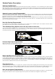
System Features Standard System Features • • • • • • • • • • • • • • • • Microprocessor Controlled Three Point Engine Immobilisation (Onboard Relays) Auto Immobilise (Passive Arming) Code Hopping Remote Technology (Anti-Scanning, Anti-Code Grabbing) Two SSR™ Solid State Remote Controls with 4 Function Operation (Arm / Disarm, Boot Release, Panic) Long Life Lithium Cell Remote Control Batteries (Each Remote Uses 2 x CR2025) Automatic Re-arm in case of Accidental Disarm Ultra-Bright Red Flashing LED Light Vi
Detailed Feature Descriptions Automatic Immobilisation The immobiliser will automatically activate 38 seconds after the ignition is switched off - This is indicated via the dash mounted LED, which will illuminate to confirm the system has entered auto immobilise mode. During this time the vehicle cannot be started until a valid remote has disarmed the system. After disarming, if the ignition is not switched on before 38 seconds have elapsed, the alarm will again go into auto immobilise mode.
Pre-Alert (2 Stage) Car Body Impact Warning with ETS™ This special feature provides a two-stage impact sensing system. It gives the security conscious owner a sensitive car body impact sensor that will give a potential thief prior warning that the vehicle is protected by this most formidable alarm system. On detection of a low level impact i.e. from a tyre kick, the siren will simply beep for a few seconds to warn away the would-be thief.
Alarm Operation Remote Control Functions: Remote Control Symbols ⁄ Action on Alarm Arm/Disarm the Alarm System Hold for Boot Release Alarm Panic Mode Optional Optional 4th Channel for Home Alarm 6
Arming and Disarming Your Immobilizer TO ARM YOUR IMMOBILISER (& lock your vehicle if central locking is connected) button on the remote control transmitter activates the immobiliser. The blinkers will flash once Pressing the ⁄ and the siren will beep once. For silent arm / disarm press ⁄ and both buttons If central locking is connected, your doors will lock. The dash LED-light will stay on for 20 seconds then flash, THE IMMOBILISER IS NOW ON. … LED COMES ON……….and after 20 seconds starts to flash.
Overriding the Immobiliser PROCEDURE: Your alarm has been loaded with a randomly generated 5 digit override code. This feature enables the owner to override their immobiliser and start the vehicle in the case of lost or damaged remote controls. The customer must be made aware of this code, which is placed, on the front of this manual and the supplied override code card. To enter your override code: 1. Enter the vehicle.
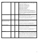
How to Change REGISTER 1: Vehicle Set Up: ALL DOORS CLOSED AND THE IGNITION TURNED ON LAST Remote Key action: TURN ON / OFF FEATURES VIA THE BUTTON ON THE REMOTE FEATURE Arming & Disarming Beeps Door Lock on Ignition (Anti-Hijack) Press Remote This Many Times 1 3 FACTORY SETTING DESCRIPTION ON OFF 1 beep on Arm & 2 beeps on Disarm. When this feature is on, the doors will lock when the ignition is turned to on, and unlock when the ignition is turned to off.
PAT™ Past Alarm Trigger Memory 13 SELECT to replay memory Current Sense Override 15 ON After pressing the remote 13 times to enter this mode, turn the ignition off. Your Rhino Alarm offers a unique memory that stores the ten last reasons why the alarm was triggered. This memory cannot be erased.
How to Change REGISTER 2: DRIVER’S DOOR OPEN, AND THE IGNITION TURNED ON LAST Vehicle Set Up: Remote Key action: TURN ON / OFF FEATURES VIA THE BUTTON ON THE REMOTE Press Remote This Many Times 2 FACTORY SETTING DESCRIPTION OFF Impact Sensor Automatic Rearm & Relock 3 4 ON OFF Timed Negative on Arm (Headlight Timer – 15 sec) 5 OFF Selectable Indicator Flash 6 ON Extended Lock Pulse (Central Closure) 7 OFF Extended Unlock Pulse 8 OFF This is activated if you have two cars with Rhino remote
Installation “RES2001” Insurance Requirements Some Insurance Companies in Australia will now specify that they require a Rhino Model “RES2001” Immobiliser to be professionally fitted to their client’s vehicles before they will insure the vehicle for theft. The code RES2001 has been especially given to insurance companies to make sure that their specified installation of a RAv3 is carried out to their client’s vehicles. If a customer says they need to have an RES2001 fitted this means that you must: 1.
Factory Remote Interface Pin Connection 1 2 3 M1 M2 POS1 4 5 6 POS2 NEG1 NEG2 Modes of Operation: Inhibit mode (Register 1 Feature 10): In inhibit mode the alarm will be armed and disarmed by M1/M2 and POS1/POS2. If a negative signal is detected by NEG1 or NEG2 arming or disarming will be inhibited. NEG1 and NEG2 would normally be hooked up to the negative switch wires from the door or a lock/unlock switch in the car.
Enable mode (Register 1, Feature 10): In enable mode the POS1 wire must see a positive signal to enable the system to arm or disarm. This is often hooked up to the indicators if they flash on arming or disarming. Wire Enable mode POS1 Positive arm POS2 Positive enable: this wire must go positive, or stay positive to arm/disarm alarm NEG1 Negative arm NEG2 Negative disarm M1 Positive disarm M2 Disarm: doesn’t require enable wire to disarm. Need to see any change of state.
WIRING INFORMATION Wire Number 12 1 and 14 (2 Wires) 17, 15 & +LED (3 Wires) 16 18 19 20 21 CONNECTION Unlock COM – Polyfused 3A unlock relay common. Refer to diagrams contained later in this manual for central locking connection GND Connect to a suitable earth on the car body. 12V Connect to constant +12 volts via the fuse box or from behind the ignition keybarrel.
Installing the Coded Battery Backup Siren (BBSC / MiniBBSC): RED +12V: Connect to constant 12V power BLACK GND: Connect to vehicle ground WHITE GREEN BROWN SIREN: Connect to wire 16 on main unit -ALARM: Negative on alarm output BONNET: Connect to wire 20 on main unit BONNET: Connect to bonnet switch Red - 12V Siren Power: Connect to permanent 12v power source – a spare GND wire is available from the main alarm loom to assist ease of wiring.
Installing Timed Headlight Delay Note: A 40 Amp Changeover Relay is required. Connecting to an Existing Electric Boot (Trunk) Release Motor Note: A 40 Amp Changeover Relay is required.
Connecting the Vehicle’s Door Switch to the Immobiliser: VEHICLES FITTED WITH AN INTERIOR LIGHT DELAY IMPORTANT NOTE: Vehicles fitted with an interior light delay require a diode to be added to prevent the system giving a door ajar warning.
Central Door Lock Diagrams 1. Negative pulse CDL system: Unlock NC Unlock COM Unlock NO Lock NC Lock COM Lock NO Cut Connect to unlock wire of vehicle Earth Cut Connect to lock wire of vehicle Earth 2. Positive pulse CDL system: Unlock NC Unlock COM Unlock NO Lock NC Lock COM Lock NO Cut Connect to unlock wire of vehicle +12V (Fused 10A) Cut Connect to lock wire of vehicle +12V (Fused 10A) 3.
5. Single wire CDL system: Unlock NC Unlock COM Unlock NO Lock NC Lock COM Lock NO Cut Connect to relay side of control wire Earth Connect to door side of control wire Connect to Unlock COM Cut 6.
WARRANTY TERMS & CONDITIONS RhinoCo Technology (The Company) warrants its products to be in conformance with its own plans and specifications and to be free from defects in materials and workmanship under normal use and service for 12 months from the date stamp control on the product, or for products not having a date stamp, for twelve months from the date of original purchase unless the installation instructions or catalogue sets forth a shorter period, in which case the shorter period shall apply.