
Instructions / Assembly

26
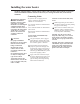
Installation Checklist
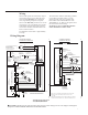
A. Water Heater Location
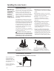
B. Water Supply
C. Gas Supply
D. Relief Valve
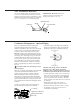
E. Venting
❑ In a location where the vent system will be
within the requirements specified this manual.
❑ Indoors and protected from freezing
temperatures.
❑ Proper clearance from combustible surfaces
observed and water heater not installed on
carpeted floor.
❑ Sufficient fresh air supply for proper
operation of water heater.
❑ Air supply free of corrosive elements and
flammable vapors.
❑ Provisions made to protect area from water
damage.
❑ Sufficient room to service heater.
❑ Combustible materials, such as clothing,
cleaning materials, rags, etc. clear of the base
of the heater.
❑ Clearances of 1 in. (2.5 cm) from combustion
air inlet openings observed
❑ Flammable vapor sensor is not blocked.
❑ Water heater completely filled with water.
❑ Air purged from water heater and piping.
❑ Water connections tight and free of leaks.
❑ Gas line equipped with shutoff valve, union
and sediment trap.
❑ The required inlet gas pressure to the water
heater is shown on the water heater rating
plate.
❑ Soap and water solution used to check all
connections and fittings for possible gas leak.
❑ Gas Company inspected installation (if
required).
❑ Temperature and Pressure Relief Valve
properly installed and discharge line run to
open drain.
❑ Discharge line protected from freezing.
❑ Water Heater vented separately from all other
appliances.
❑ Blower assembly properly installed.
❑ Proper materials and techniques used in vent
assembly.
❑ Vent pipe properly secured to exhaust
connector of the blower assembly.
❑ Vent system supported at required intervals.
❑ Appropriate minimum clearances observed.
❑ Precautions taken to prevent moisture damage
around vent termination.
❑ Vapors from non-metallic pipe cement and
primer have dissipated prior to applying
electrical power.
F. Wiring
❑ Correct power supply (120 V).
❑ Electrical connections tight.
❑ Heater properly grounded and proper polarity
observed.