
Instructions / Assembly

21
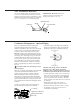
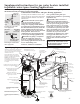
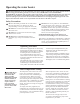
Vent Termination Restrictor
These water heater models are supplied with 2 in
(5.1 cm) vent termination restrictor. The restrictor
helps the water heater achieve peak efciency when
installed at the minimum equivalent vent length of
7 ft. (2.1 m) using 2 in. (5.1 cm) diameter pipe.
IMPORTANT: DO NOT install the ter-
mination restrictor in equivalent vent
lengths longer than 7 ft. (2.1 m).
Vent Pipe
Mesh
Vent Restrictor
Vent Terminal
Condensate Management - Optional Piping
There is no condensate collection and disposal
required for Rheem water heaters under most
conditions. Installations where the vent system length
is short or where it runs through conditioned space
in the home, such as basements or interior walls,
DO NOT typically cause condensation and will not
require any condensation disposal methods regardless
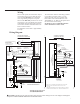
of vent pipe slope. The image on page 17 shows the
recommended vent pipe slope of no less than 1/8 in.
per foot (10 mm per m) away from the water heater.
Any condensation in the venting system will drain
toward the vent termination. The blower assembly
features a capped drain port, which is not needed in
this case.
CAUTION: Make sure the drain port cap is
securely in place.
There are vent piping configurations, when combined
with certain environmental conditions that can
produce enough condensate to require collection
and disposal. When a slope away from the water
heater cannot be achieved and condensate handling
is required in a horizontal vent system, slope the vent
pipe toward the water heater 1/8 in. per foot (10 mm
per m) minimum and condensate management means
as follows:
• Using a set of pliers, remove the clamp and cap
from the drain port from the blower assembly.
• Connect the tubing with clamp to the condensate
drain port. Ensure that the clamp securely fastens
the tubing to the blower's condensate drain port.
NOTICE: The tubing must be of sufficient
length to reach a floor drain, outside the
building or other required condensate disposal
termination requirements (Refer to local codes).
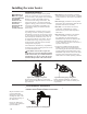
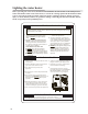
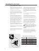
• Loop the drain tube so that it has a circular trap
and secure the top and bottom of the loop with
wire ties or plastic zip ties as shown. DO NOT
restrict any portion of the drain tube. The loop
and all sections of the tube must not be restricted
or collapsed.
• Fill the drain tube with water so that no
combustion gases might vent into the room.
• Route the drain tube to a floor drain or outside
the building or refer to local codes for any
condensation requirements.
From Drain Port
To Floor Drain
Wire or
Zip Ties
Water
Filled
Clamp
Optional Condensate
Management Drain
Port Cap