
Instructions / Assembly

17
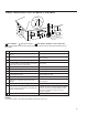
-B-
d
.008
d
.010
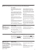
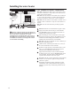
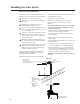
Horizontal Vent Installation
Read these instructions thoroughly and make
sure you understand all steps and procedures
before proceeding with the installation.
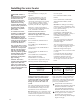
Determine the locations for the vent ter-
minal then make a hole through the exte-
rior wall to accommodate the vent pipe.
• Maintain a minimum horizontal dis-
tance of 12 in. (30.5 cm) between the
vent terminal centerline. Insert vent
pipe through the wall as shown.
• Allow sufcient length of pipe to extend
beyond the exterior wall of the build-
ing for attachment of the vent terminal.
Place the supplied mesh metal screen
inside each terminal tting.
NOTICE: For cold climates, the
screen may be removed.
Connect the terminal to the vent pipe,
which extends out of the building.
• Ensure that the back of the supplied termi-
nal is ush with the outside wall surface.
Complete the installation of the remainder of the
vent system and attach it to the vent connector
tting on the water heater’s blower assembly.
• Horizontal lengths of the vent sys-
tem must slope downward a minimum
of 1/8 in. per foot (10 mm per m);
IMPORTANT: When the vent system can-
not be sloped away from the water heater or,
if the vent system has vertical section(s), then
all horizontal sections must slope upwards a
minimum of 1/8 in. per foot (10 mm per m);
DO NOT use unequal diameters of
pipe and ttings for the vent sys-
tem except as dened previously.
Support vertical and horizontal lengths of
the vent system as previously mentioned.
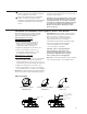
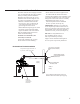
2 ft. x 2 ft. (60 cm x 60 cm) Sheet
Metal Shield on Brick or Masonry
Walls
Outside of
Building
Terminals with Mesh Protective
Screens Inside and Termination
Restrictors Inside.
Inside of
Building
Rear of Termination Flush
with Outside of Wall
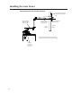
Horizontal Vent Terminal Installation
Slope horizontal pipe downward 1/8
in. per foot (10 mm per m) min.
Optional
Condensate
Management
Drain Port*
*See Condensate Management Section for
additional information about optional piping.