
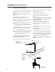
Instructions / Assembly

15
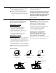
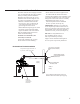
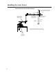
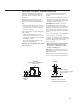
Other Than Direct Vent Terminal Clearances
Regulator vent outlet in the event no
regulator is present, H and I can be
disregarded.
Fixed
closed
15 ft
Fixed
closed
Inside
corner detail
Operable
Operable
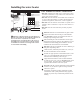
The following information should be used for determining the proper location of the vent terminal for other than direct vent
water heaters.
V
VENT TERMINAL
X
AIR SUPPLY INLET
AREA WHERE TERMINAL IS NOT PERMITTED
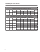
US Installations
1
A=
Clearance above grade, veranda, porch, deck, or
balcony.
12 in (30 cm)
B= Clearance to window or door that may be opened.
4 ft (1.2 m) below or to side of opening; 1 ft (300 mm)
above opening
C= Clearance to permanently closed window 0 in (0 cm)
D=
Vertical clearance to ventilated soffit located above
the terminal within a horizontal distance of 2 feet (61
cm) from the center line of the terminal
12 in (30 cm)
E= Clearance to unventilated soffit 12 in (30 cm)
F= Clearance to outside corner 24 in (61 cm)
G= Clearance to inside corner 18 in (45 cm)
H=
Clearance to each side of center line extended above
meter/regulator assembly
3 ft (91 cm) within a height 15 ft (45 cm) above the
meter/regulator assembly
I= Clearance to regulator vent outlet 3 ft (91 cm)
J=
Clearance to non-mechanical air supply inlet to
building or the combustion air inlet to any other
appliance
4 ft (1.2 m) below or to side of opening; 1 ft (300 mm)
above opening
K= Clearance to a mechanical air supply inlet 3 ft (91 cm) above if within 10 ft (3 m) horizontally
L=
Clearance above paved sidewalk or paved driveway
located on public property
7 ft (2.13 m) for mechanical draft systems (Category
I appliances); vents for Category II and IV appliances
cannot be located above public walkways or other
areas where condensate or vapor can cause a
nuisance or hazard
M= Clearance under veranda, porch deck, or balcony 12 in (30 cm)
Notes:
1
In accordance with the current ANSI Z223.1/NFPA 54, National Fuel Gas Code.