
Instructions / Assembly

13
Check the vent for signs of sagging or other
stresses in the joints as a result of misalignment
of any components in the systems.
If any of the conditions above are found, they
must be corrected in accordance with the
instructions in this manual before completing the
installation and putting the water heater into
service.
Additional installation information for The
Commonwealth of Massachusetts is located on the
back page of this manual.
NOTICE: The vent piping must be connected to
the blower assembly using the rubber coupling
and supplied clamp. The vent pipe connection
at the blower assembly must be leak tested with
soap and water solution upon initial startup.
Repair any leaks before allowing the water
heater to operate.
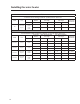
Maximum and Minimum Vent Lengths for Power Vent Models:
Read these instructions thoroughly and make
sure you understand all steps and procedures
before proceeding with the installation.
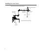
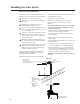
When using 2 in. (5.1 cm) di-
ameter pipe and ttings:
1. Connect the vent system piping to the
blower assembly using the already in-
stalled 2 in. (5.1 cm) diameter rubber
coupling and clamp. (See Figure 1).
2. Tighten the clamp between 30 to 40 in. lbs.
3. For the vent terminal, use the 2 in. (5.1
cm) diameter, Schedule 40, PVC, 45° el-
bow supplied with the water heater.
When using 3 in. (7.6 cm) di-
ameter pipe and ttings:
1. Install a straight length of 2 in. (5.1 cm) diameter
pipe to the rubber coupling on the blower as-
sembly, followed by a 2 in. (5.1 cm) to 3 in. (7.6
cm) diameter pipe increaser tting (See Figure 2).
2. Tighten the clamp between 30 to 40 in. lbs.
3. For the vent terminal, use a 3 in. (7.6 cm) diam-
eter, Schedule 40, PVC, 45° elbow (not supplied).
DO NOT use unequal diameters of pipe and ttings
for the vent systems except as dened previously.
IMPORTANT: Ensure that the coupling clamp is
tight before allowing the water heater to operate.
When using CPVC or ABS pipe and t-
tings, use 90° elbows of the corresponding
size and material for the vent terminal.
The minimum and maximum equivalent lengths
for the vent system are shown in Table 1.
• The vent termination is not included
in the equivalency calculations.
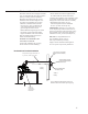
NOTICE: A 90°, 1/4 standard bend or
long bend elbow is equivalent to 5 ft.
(1.52 m) of straight pipe. A 45°, 1/8 stan-
dard bend or long bend elbow is equiva-
lent to 2.5 ft. (0.76 m) of straight pipe.
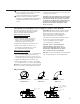
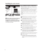
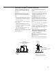
DO NOT use short bend elbows. Use only standard
and/ or long bend elbows. See examples below
Elbow Examples
Short Bend 90° Elbow
DO NOT Use
Figure 1 Figure 2
Standard Bend 90° Elbow
OK to Use
Long Bend 90° Elbow
OK to Use
2 in. (5.1 cm)
pipe
2 in. (5.1 cm)
pipe
2 in. (5.1 cm) to
3 in. (7.6 cm) Pipe
Increaser