! WARNING: This water heater is not suitable for use in manufactured (mobile) homes! Use & Care Manual With Installation Instructions for the Installer Residential Gas - FVIR Certified ® Water Heaters The purpose of this manual is twofold: one, to provide the installer with the basic directions and recommendations for the proper installation and adjustment of the water heater; and two, for the owner–operator, to explain the features, operation, safety precautions, maintenance and troubleshooting of the
Safety Information Safety Precautions. . . . . . . 3–6 LP Gas Models . . . . . . . . . . . . 5 FOR YOUR RECORDS Write the model and serial numbers here: # Installation Instructions # Location. . . . . . . . . . . . . . . . . . 7 You can find them on a label on the appliance. Water Supply Connections. . . 9 Staple sales slip or cancelled check here. Gas Supply. . . . . . . . . . . . . . . 11 Proof of the original purchase date is needed to obtain service under the warranty. Venting. . . . . . . .
IMPORTANT SAFETY INFORMATION. READ ALL INSTRUCTIONS BEFORE USING. Be sure to read and understand the entire Use and Care Manual before attempting to install or operate this water heater. It may save you time and money. Pay particular attention to the Safety Instructions. Failure to follow these warnings could result in serious bodily injury or death.
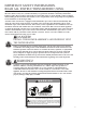
IMPORTANT SAFETY INFORMATION. READ ALL INSTRUCTIONS BEFORE USING. ! DANGER! WATER TEMPERATURE SETTING Safety and energy conservation are factors to be considered when selecting the water temperature setting of a water heater’s gas control. Water temperatures above 125°F can cause severe burns or death from scalding. Be sure to read and follow the warnings outlined on the label pictured below. This label is also located on the water heater.
DANGER! LIQUEFIED PETROLEUM (LP PROPANE OR BUTANE) AND NATURAL GAS MODELS LP and Natural gas have an odorant added to aid in detecting a gas leak. Some people may not physically be able to smell or recognize this odorant. If you are unsure or unfamiliar with the smell of LP or natural gas, ask the gas supplier. Other conditions, such as “odorant fade”, which causes the odorant to diminish in intensity, can also hide or camouflage a gas leak.
IMPORTANT SAFETY INFORMATION. READ ALL INSTRUCTIONS BEFORE USING. ! WARNING! For your safety, the information in this manual must be followed to minimize the risk of fire or explosion, electric shock, or to prevent property damage, personal injury, or loss of life. FOR INSTALLATIONS IN THE STATE OF CALIFORNIA California Law requires that residential water heaters must be braced, anchored or strapped to resist falling or horizontal displacement due to earthquake motions.
Installing the water heater This water heater must be installed in accordance with these instructions, local codes, utility company requirements, and/or in the absence of local codes, use the latest edition of the American National Standard/National Fuel Gas Code. A copy can be purchased from either the American Gas Association, 400 N. Capitol Street NW, Washington, DC 20001 as ANSI standard Z223.1 or National Fire Protection Association, 1 Batterymarch Park, Quincy, MA 02269 as booklet NFPA 54.
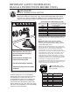
Installing the water heater Combustion and Ventilation Air Proper operation of the water heater requires air for combustion and ventilation. Provisions for combustion and ventilation air must comply with referenced codes and standards. DO NOT block or obstruct any of the combustion air inlet openings located around the perimeter of the water heater. A minimum of 1 in. (2.54 cm) is required between these combustion air inlet openings and any obstruction.
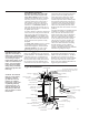
Thermal Expansion Determine if a check valve exists in the inlet water line. Check with your local water utility company. It may have been installed in the cold water line as a separate back flow preventer, or it may be part of a pressure reducing valve, water meter or water softener. A check valve located in the cold water inlet line can cause what is referred to as a “closed water system”. A cold water inlet line with no check valve or back flow prevention device is referred to as an “open” water system.
Installing the water heater A new combination temperature and pressure relief valve, complying with the Standard for Relief Valves for Hot Water Supply Systems, ANSI Z21.22/CSA 4.4, is factory installed and must remain in the opening provided and marked for the purpose on the water heater. No valve of any type should be installed between the relief valve and the tank.
WARNING: DO NOT attempt to convert this water heater for use with a different type of gas other than the type shown on the rating plate. Such conversion could result in hazardous operating conditions. Gas Supply The branch gas supply line to the water heater should be clean properly sized steel pipe or other approved gas piping material. A union or ANSI design certified semirigid or flexible gas appliance connector should be installed in the gas line close to the water heater.
Installing the water heater Venting DANGER: Failure to install the blower assembly if shipped detached from the water heater and properly vent the water heater to the outdoors as outlined in the Venting section of this manual will result in unsafe operation of the water heater causing bodily injury, explosion, fire or death.
Check the vent for signs of sagging or other stresses in the joints as a result of misalignment of any components in the systems. Additional installation information for The Commonwealth of Massachusetts is located on the back page of this manual. If any of the conditions above are found, they must be corrected in accordance with the instructions in this manual before completing the installation and putting the water heater into service.
Installing the water heater Table 1 From Sea Level through 2,000 Ft. (609 m) Above Sea Level Model All Gas Natural & Propane Heater Input Vent System Diameter Min. Allowed Equivalent Vent Length Max. Allowed Equivalent Vent Length Btu/hr. Inches Feet Meters Feet Meters 42,000 40,000 36,000 32,000 2 7 2.1 55 16.7 45° Elbow 3 7 2.1 150 45.7 45° Elbow Vent System Termination From 2,000 Ft. (609 m) through 7,800 Ft.
Other Than Direct Vent Terminal Clearances Inside corner detail 15 ft Fixed Operable closed Fixed closed Operable Regulator vent outlet in the event no regulator is present, H and I can be disregarded. V VENT TERMINAL X AIR SUPPLY INLET AREA WHERE TERMINAL IS NOT PERMITTED The following information should be used for determining the proper location of the vent terminal for other than direct vent water heaters. US Installations 1 A= Clearance above grade, veranda, porch, deck, or balcony.
Installing the water heater Vent Terminal Location Considerations Caulk Rising moisture will collect under eaves Inside corner If soffit vent is too close, block off and install new vent at another location Caulk 12” (30,5cm) min. above grade or anticipated snow level 4’ (1.2 m) 6ft. (1.8 m) Caulk zone or to edge of window etc., starting within 6 ft. (1.8 m) Vent Vent WARNING : Moisture in the flue gas will condense as it leaves the vent terminal.
Horizontal Vent Installation Read these instructions thoroughly and make sure you understand all steps and procedures before proceeding with the installation. Determine the locations for the vent terminal then make a hole through the exterior wall to accommodate the vent pipe. • Maintain a minimum horizontal distance of 12 in. (30.5 cm) between the vent terminal centerline. Insert vent pipe through the wall as shown.
Installing the water heater Alternate Horizontal Vent Terminal Installation 2 ft. x 2 ft. (60 cm x 60 cm) Sheet Metal Shield on Brick or Masonry Walls Raise horizontal pipe upwards 1/8 in. per foot (10 mm per m) min. Raise horizontal pipe upwards 1/8 in. per foot (10 mm per m) min. Inside of Building d Rear of Termination Flush with Outside of Wall Outside of Building .008 -Bd .010 *See Condensate Management Section for additional information about optional piping.
Horizontal Vent Riser Terminal Installation Read these instructions thoroughly and make sure you understand all steps and procedures before proceeding with the installation. Determine the locations for the vent terminal then make a hole through the exterior wall to accommodate the vent pipe. • Maintain a minimum distance from the vent terminal of not less than 1 ft. (30.5 cm) above grade or average snowfall whichever is greater. Insert length of the vent pipe through the wall as shown.
Installing the water heater Vertical Vent Installation The location of the vent terminal depends on the following minimum clearances and considerations. make a hole through the roof and interior ceiling(s) to accommodate the vent pipe. Minimum 12 in. (30.5 cm) above roof. Assemble the vent pipe assembly. M inimum 12 in. (30.5 cm) above anticipated snow level. Install the vent system and attach it to the vent connector fitting on the water heater’s blower assembly. Maximum 24 in.
Vent Termination Restrictor These water heater models are supplied with 2 in (5.1 cm) vent termination restrictor. The restrictor helps the water heater achieve peak efficiency when installed at the minimum equivalent vent length of 7 ft. (2.1 m) using 2 in. (5.1 cm) diameter pipe. Vent Pipe Mesh IMPORTANT: DO NOT install the termination restrictor in equivalent vent lengths longer than 7 ft. (2.1 m).
Installing the water heater NOTICE: All pipe, fittings, solvent cement, primers and procedures must conform to American National Standards Institute and American Society for Testing and Materials (ANSI/ASTM) standards. Cementing Joints WARNING: DANGER OF FIRE OR BODILY INJURY - Solvent cements and primers are highly flammable. Provide adequate ventilation and DO NOT assemble near heat source or open flame. DO NOT smoke. Avoid skin or eye contact. Observe all cautions and warnings on material containers.
Wiring If local codes permit, the water heater may be connected to electric service with the power cord provided (DO NOT use an extension cord). A grounding receptacle is required. If local codes DO NOT permit the use of cord connections, a 120 V, 50/60 Hz power supply, with suitable disconnecting means, must be connected to the black and white leads in the heater control enclosure.
Installing the water heater Insulation Blankets WARNING: If local codes require external application of insulation blanket kits the manufacturer’s instructions included with the kit must be carefully followed. Insulation blankets, available to the general public, for external use on gas water heaters are not necessary. The purpose of an insulation blanket is to reduce the standby heat loss encountered with storage tank heaters.
Heat Traps For increased energy efficiency, some water heaters have been supplied with factory installed 3/4 in. NPT heat trap fittings in the hot outlet line and cold water inlet line. These heat trap fittings may require 90° 3/4 in. NPT elbow(s) 3/4 in. coupling(s) depending on your installation needs. See Illustration of nipples and heat traps on page 38. During Installation of this water heater...........
Installation Checklist A. Water Heater Location ❑ In a location where the vent system will be within the requirements specified this manual. ❑ Indoors and protected from freezing temperatures. ❑ Proper clearance from combustible surfaces observed and water heater not installed on carpeted floor. ❑ Sufficient fresh air supply for proper operation of water heater. ❑ Air supply free of corrosive elements and flammable vapors. ❑ Provisions made to protect area from water damage.
Supplemental instructions for gas water heaters installed in potable water/space heating applications. Local codes or plumbing authority requirements may vary from the instructions or diagrams provided in this manual and take precedent over these instructions. Hot water supply to house Hot water supply to heating unit From HOT outlet on water heater Tee fitting for vertical hot water supply lines.
Lighting the water heater Before operating this water heater, be sure to read and follow the instructions on the label pictured below and all other labels on the water heater, as well as the warnings printed in this manual. Failure to do so can result in unsafe operation of the water heater resulting in property damage, personal injury, or death. Should you have any problems reading or following the instructions in this manual, STOP, and get help from a qualified person.
Operating the water heater CAUTION: Hydrogen gas can be produced in a hot water system served by this water heater that has not been used for a long period of time (generally two weeks or more). HYDROGEN GAS IS EXTREMELY FLAMMABLE!! To dissipate such gas and to reduce risk of injury, it is recommended that the hot water faucet be opened for several minutes at the kitchen sink before using any electrical appliance connected to the hot water system.
Operating the water heater Water Temperature Setting… Maximum water temperatures occur just after the burner has shut off. To determine the water temperature, turn on a hot water faucet and place a thermometer in the water stream. If an adjustment to the water temperature is preferred, then refer to the Water Heater User Display – Operation Instructions for instruction on adjusting the local and remote user display temperature setpoints.
Sequence of Operation… 1. During initial start-up or a call for heat, the control will verify the vacuum switch is open. This water heater is equipped with a flammable vapor sensor that is monitored continuously by the electronic control in all modes of operation. 2. Once the control verifies the blower vacuum switch is open, the control will energize the blower motor for the pre-purge sequence (approximately 5 seconds).
Care and cleaning of the water heater Draining the Water Heater ! CAUTION: Shut off gas to the water heater at the gas control (thermostat) gas cock or manual shut-off valve before draining water. ! DANGER: Before manually operating the temperature and pressure relief valve, make certain no one will be exposed to the hot water released by the valve. The water drained from the tank may be hot enough to present a scald hazard and should be directed to a suitable drain to prevent injury or damage.
! DANGER: Combustible materials, such as clothing, cleaning materials, or flammable liquids, etc., must not be placed against or next to the water heater. Housekeeping Visually inspect the pilot. Make sure that the combustion air inlet openings located around the perimeter of the water heater are not blocked or obstructed. A minimum clearance of 1 in. (2.5 cm) is required between the combustion air inlet openings and any object. DO NOT obstruct or block the Flammable Vapor Sensor.
Care and cleaning of the water heater Vacation and Extended Shut-Down NOTICE: Refer to the Hydrogen Gas Caution in the Operating Instructions. If the water heater is to remain idle for an extended period of time, the power and water to the appliance should be turned off to conserve energy and prevent a build-up of dangerous hydrogen gas. The water heater and piping should be drained if they might be subjected to freezing temperatures.
Before You Call For Service… Troubleshooting Tips Save time and money! Review the charts on the following pages first and you may not need to call for service. This water heater incorporates a combustion shut off device that shuts the operation of the water heater down if undesirable combustion conditions occur, such as the presence of flammable vapors or blockage of the vent and/or combustion air-inlet openings. Please contact a Qualified Service Technician if this occurs.
Before You Call For Service… Troubleshooting Tips Save time and money! Review the charts on the following pages first and you may not need to call for service. This water heater incorporates a combustion shutoff device that shuts the operation of the water heater down if undesirable combustion conditions occur, such as the presence of flammable vapors or blockage of the vent and /or combustion air inlet openings. Please contact a Qualified Service Technician if this occurs.
Gas Valve LED Codes LCD CODE (Models equipped with optional display) None None LED STATUS Short flash once every four seconds “Heartbeat”, alternates bright/dim 12 One flash every three seconds 44 Two flashes every three seconds 46 Three flashes every three seconds 31 Four flashes every three seconds 14 Five flashes every three seconds 11 Six flashes of one, every three seconds 45 13 14 10 47 49 89 15 93 PROBLEM SOLUTION None No solution required None No solution required 1.
Replacement Parts For 40 and 50 gallon models equipped for use with Natural or Liquefied Petroleum / LP gas. Instructions For Placing a Parts Order All parts orders should include: he model and serial number of the T water heater from the rating plate. pecify type of gas (Natural or S Liquefied Petroleum / LP gas) as marked on the rating plate. art description (as noted below) and P number of parts desired.
Notes...
IF YOU NEED SERVICE 1 S hould you have any questions about your new water heater, or if it requires adjustment, repair, or routine maintenance, it is suggested that you first contact your installer, plumbing contractor or previously agreed upon service agency. In the event the firm has moved, or is unavailable, refer to the telephone directory, commercial listings or local utility for qualified service assistance. 2.