
Instructions / Assembly

15
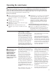
For increased energy efficiency, this water heater
has been supplied with a 2 3/8” section of T&P
insulation. Please install the insulation as shown
below.
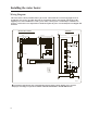
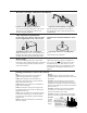
T&P Insulation Installation
Typical Side Connect T & P Arrangement.
Slip the insulation cover over the T&P Valve
through the center hole and align the hole in
the side with the opening of the T&P Valve.
Ensure the T&P Valve opening is not
obstructed by the insulation.
Typical Top Connect T & P Arrangement.
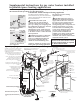
Hot and Cold Pipe Insulation Installation
For increased energy efficiency, some water
heaters have been supplied with two 24”
sections of pipe insulation.
Please install the insulation, according to
the illustrations above, that best meets your
requirements.
Typical vertical piping arrangement
Typical horizontal piping arrangement
Heat Traps
For increased energy efficiency, some water
heaters have been supplied with factory installed
3/4” NPT heat traps in the hot outlet line and
cold water inlet line
These heat traps may require a minimum of
one (1) 90° 3/4” NPT elbow and may require
an additional 90° 3/4” NPT elbow or a 3/4”
coupling depending on your installation needs.
See Illustration of nipples and heat traps on
page 27.
DO
❑ DO check inlet gas pressure to ensure that it is
within the range specified on the rating plate.
❑ DO provide adequate air for combustion and
ventilation as discussed in the Use and Care Manual
and the National Fuel Gas Code.
❑ DO maintain proper clearances to combustibles as
specified on the rating plate.
❑ DO ensure that the venting system complies with
the guidelines found in the Use and Care Manual and
National Fuel Gas Code.
❑ DO contact a qualified service technician if the pilot
or main burner will not stay lit. The burner chamber
is designed to be sealed utilizing a gasket and tamper
resistant screws.
❑ DO ensure that the flue damper is not obstructed
and is free of debris.
DON’T
❑ DON’T block or restrict Combustion Air Inlet
Openings located around the lower portion of the water
heater jacket.
❑ DON’T remove the Burner Access Door unless
absolutely necessary. This should only be done by a
qualified service technician. A new burner access door
gasket must be installed on any burner access door that
has been removed.
❑ DON’T install this water heater where standing
water may occur. The base of the water heater is
meant to be mounted on a dry surface.
❑ DON’T operate the water heater if the sight glass
or burner access door grommet is damaged or broken.
❑ DON'T
manually
open or
close the
damper.
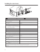
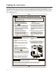
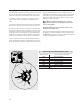
During Installation of this water heater
Burner Access
Door Grommet
Sight
Glass
Flammable
Vapor Sensor