
Instructions / Assembly


10
Installing the water heater
A new combination temperature and pressure relief valve, complying with the Standard for Relief Valves
and Automatic Gas Shut-Off Devices for Hot Water Supply Systems, ANSI Z21.22, is supplied and must
remain in the opening provided and marked for the purpose on the water heater. No valve of any type
should be installed between the relief valve and the tank. Local codes shall govern the installation of relief
valves.
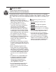
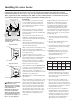
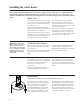
Relief Valve
The pressure rating of the relief valve must
not exceed 150 PSI, the maximum working
pressure of the water heater as marked on
the rating plate.
The Btuh rating of the relief valve must
equal or exceed the Btuh input of the water
heater as marked on its rating plate.
Position the outlet of the relief valve above
a suitable open drain to eliminate potential
water damage. Piping used should be of a
type approved for hot water distribution.
The discharge line must be no smaller
than the outlet of the valve and must
pitch downward from the valve to allow
complete drainage (by gravity) of the relief
valve and discharge line.
The end of the discharge line should not
be threaded or concealed and should be
protected from freezing. No valve of any
type, restriction, or reducer coupling should
be installed in the discharge line.
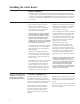
To Fill the Water Heater
Make certain that the drain valve is closed,
then open the shut-off valve in the cold
water supply line.
Open each hot water faucet slowly to allow
the air to vent from the water heater and
piping.
A steady flow of water from the hot water
faucet(s) indicates a full water heater.
DO NOT allow flammable vapor sensor to
become submerged in water.
WARNING: The tank
must be full of water before
heater is turned on. The
water heater warranty does
not cover damage or failure
resulting from operation
with an empty or partially
empty tank.
Condensation
Condensation can form on the tank when
it is first filled with water. Condensation
might also occur with a heavy water
draw and very cold inlet water
temperatures.
Drops of water falling on the burner can
produce a sizzling or pinging sound.
This condition is not unusual, and will
disappear after the water becomes heated.
If, however, the condensation continues,
examine the piping and fittings for possible
leaks.
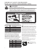
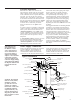
This water heater has a factory installed
flue damper device for increased energy
efficiency. Removal of the flue damper
connections will render the heater
inoperable. DO NOT operate the water
heater without the damper housing in
place on the damper assembly. A draft
hood is shipped with this water heater.
The draft hood must be installed on the
damper housing using the holes provided
for alignment and fastening. The damper
must be in open position as shown in the
figure when water heater main burner is
operating. See trouble shooting instructions
if a condition other than this occurs.
Flue Damper
Follow these instructions for proper installation and operation