
Installation Guide
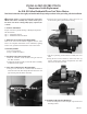

b. Disconnect the two female, wiring terminal connectors
from the temperature switch.
6. TEMPERATURE SWITCH INSTALLATION
a. Locate the new temperature switch from the Service Parts
Kit.
IMPORTANT: Your temperature switch and its setting may
be different from the one removed or shown above.
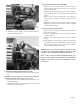
b. Connect the two female, wiring terminal connectors to the
temperature switch.
c. Reposition the temperature switch back into its mounting
bracket on the blower assembly.
7. VENT PIPE AND HOUSING ASSEMBLY
a. Replace the control compartment door back onto the
blower assembly then reinstall the three (3) screws that
secure the door in place.
b. Replace the top housing back onto the blower assembly
then reinstall the seven (7) screws that secure the housing
in place.
c. Ensure that the rubber coupling in the vent outlet is in
place and in good condition and shows no signs of cracks
or tears
d. Reinstall the vent pipe or fitting into the blower coupling
making sure that the vent pipe is fully seated then tighten
the hex head, band clamp.
8. POWER SUPPLY CONNECTION
a. Plug in the electrical supply cord of the blower assembly
to the electrical supply.
b. Slide the “ON/OFF” switch located on the gas control to
the “ON” Position.
c. Rotate the gas control, temperature knob to the desired
setting.
d. If the appliance will not operate, follow the instructions
“TO TURN OFF GAS TO APPLIANCE” found on mark-
ings on the water heater and in the Use & Care Manual
that was supplied with the water heater.
IMPORTANT: Use of this kit requires the first 10 feet
equivalent of vent pipe and/or fittings be of CPVC or ABS.
See the Use & Care Manual for additional information.
Refer to the Use and Care Manual supplied with the water
heater for the remainder of information on the installation,
lighting instructions, operation and maintenance of the
water heater.
AP22143