Use & Care Manual With Installation Instructions for the Installer Passive Solar Water Heating Systems The purpose of this manual is twofold: one, to provide the installer with the basic directions and recommendations for the proper installation and adjustment of the water heater; and two, for the owner–operator, to explain the features, operation, safety precautions, maintenance and troubleshooting of the water heater. This manual also includes a parts list.
Safety Information Introduction . . . . . . . . . . . . 3, 4 Safety Precautions . . . . . . . 5, 6 FOR YOUR RECORDS Write the model and serial numbers here: Installation Instructions # Location . . . . . . . . . . . . . . . . . 7 # Unit Specifications & Parts 7,8 You can find them on a label on the appliance. Pre-Installation Review. . . . . 9 Staple sales slip or cancelled check here. System Requirements . . . . .
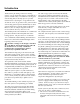
Introduction Thank you for purchasing a solar water heating system. It is one of the most effective and trouble-free systems available today. In addition to reducing your water-heating bills, it will help preserve precious natural resources by using free energy from the sun. As with an electric or gas water heater, your new solar water heating system operates automatically to ensure you will always have an ample supply of hot water.
Introduction continued... While your system is one of the most efficient available, there are two simple steps you can take to increase your water-heating cost savings. Keep the use of the Backup Heater to a Minimum You can save the most money on your water-heating bills by using the backup heater on your system as little as possible. If the sun shines brightly between I0 am and 3 pm, enough heat will normally be generated to keep the water hot throughout the rest of the day and night.
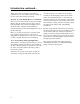
IMPORTANT SAFETY INFORMATION. READ ALL INSTRUCTIONS BEFORE USING. ! DANGER! WATER TEMPERATURE SETTING Safety and energy conservation are factors to be considered when selecting the water temperature setting of water heater’s thermostat. Water temperatures above 125°F can cause severe burns or death from scalding. Be sure to read and follow the warnings outlined on the label pictured below.
IMPORTANT SAFETY INFORMATION. READ ALL INSTRUCTIONS BEFORE USING. ! WARNING! For your safety, the information in this manual must be followed to minimize the risk of fire or explosion, electric shock, or to prevent property damage, personal injury, or loss of life. Be sure to read and understand the entire Use and Care Manual before attempting to install or operate this water heater. It may save you time and cost. Pay particular attention to the Safety Instructions.
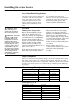
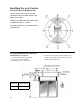
Installing the water heater. The location chosen for the water heater must take into consideration the following: Local Installation Regulations This water heater must be installed in accordance with these instructions, local codes, utility codes, utility company requirements or, in the absence of local codes, the latest edition of the National Electrical Code. ! WARNING: Heat trace will not protect against pipe freezing in the event of power loss.
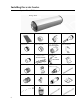
Installing the water heater. System Parts ID List Storage Tank Solar Collector 3/4” Union Nut Collector Nut 18mm Union Cone Collector Plug 8 Lag Screw (5/16” x 1 3/4”) (NOT INCLUDED) 3/4” T/P Valve 3/4” Check Valve (NOT INCLUDED) 3/4” Cold Water Expansion Valve Fill Fitting Collector Hot Pipe Collector Clamps (NOT INCLUDED) 3/4” Tail Plug Tempering Valve PR6 Jacket Relief Valve (includes “O” ring).
Pre-Installation This section will guide you to gather the necessary information to install the system correctly. Use it together with the Installation Checklist to identify all installation requirements. These installation inspection procedures include; • Plumbing requirements • Review of local building codes for site • Electrical requirements requirements and specific guidelines for plumbing and electrical installation.
Installing the water heater. System Placement Requirements The system must face between 135 - 225° (Ideal direction is true South): (Refer to the Figure on the right). Installations outside this range require either an additional collector or frame. Site must be shade-free year-round and clear of obstructions. Area Requirements for Collectors Plumbing/Electrical stub-out • 1' 6" left side for roof-ridge mount, • 1' 6" top or left side all others. • Maintenance area: 8' on left side.
Pitch Requirements Correct operation requires a 15°- 45° pitch (slope). This can be done by using the roof slope itself or a frame ! CAUTION: DO NOT install on a roof with a pitch beyond 45°. Use pitch gauge and compass and complete the following steps. Record the results on the checklist. • Record pitch and compass bearing of proposed installation site. • Using table shown below, select number of collectors and correct type of installation.
Installing the water heater. Roof Survey NOTICE: A roof in poor condition may need replacement before the system is installed. Record the following on the checklist: • The type of roofing material (tile, shingle, tar & gravel, metal, etc.). • The condition of the roof. Note any repair requirements needed prior to installation. • Draw diagram (top view) as shown below, of installation area. Mark location of the system and stub-out.
Conventional Roof Modifications Truss Frame Modifications Determine the correct truss frame modification using the figures shown below. Allowable Spans for Trusses 2” x 4” Top Chord 2” x 6” Top Chord 24” O.C.
Installing the water heater. Review the checklist for installation requirements. Check the following before beginning installation. Permits Obtain required permits before installation. Work Force An 80 gallon storage tank weighs up to 242 lbs empty, requiring a crew of two or more to install. Inventory Review Section on Frames, included hardware, and all optional supplies before beginning installation.
Electrical System Requirements NOTICE:All wiring must conform to local codes or the latest edition of National Electrical Code ANSI/NFPA 70. ! WARNING: Any wiring outside of the house should be rated for the appropriate weather conditions. If the system is being used as a pre-heater to an existing water heater, the electrical review and installation may not be required.
Installing the water heater. A new combination temperature and pressure relief valve, complying with the Standard for Relief Valves and Automatic Gas Shut-Off Devices for Hot Water Supply Systems, ANSI Z21.22, is supplied and must be installed in the opening provided and marked for the purpose on the water heater. No valve of any type should be installed between the relief valve and the tank. Local codes shall govern the installation of relief valves.
Plumbing System Schematic for Replacement of Existing Electric Water Heater T/P 3/4” Tank 3/4” Collector Collector Valve Settings: Solar Only = (TWV1-1) + (TWV2-1) + (Pre Heat OFF) Storage Only = (TWV1-2) + (TWV2-2) + (Pre Heat OFF) Solar Pre Heat = (TWV1-1) + (TWV2-2) + (Pre Heat ON) TWV1 = Two Way Valve - 1 Inlet Selector TWV2 = Two Way Valve - 1 Outlet Selector Pre Heat = Solar Pre Heat Valve M = Mixing Valve T/P = Temperature & Pressure Relief Plumbing System Schematic for Installation of stand a
Installing the water heater. Plumbing System Schematic for Installation as Pre Heater T/P 3/4” 3/4” Collector Collector Notice: All pipe work 3/4” unless otherwise stated.
Roof Preparation This section contains instructions for correct installation of the system. Complete the procedures in the order listed. NOTICE: The storage tank will be parallel to rafters of trusses for sidepitch mount and at a right angle for all other mounts. Refer to the checklist for necessary roof modifications on page 12. clearance on each side (refer to Figure below) set aside for reinstallation. Install supports for Fragile Tile Roof Install waterproof material over cleared area.
Installing the water heater. Wood Runner Detail for 16” & 24” On-Center Rafters for Standard Installation Collector Extrusion Detail for Standard Installation ! CAUTION: The Extrusion must slope 1/2” per collector from horizontal (hot pipe side to be higher) for the system to work correctly. Metal or Tile Installation NOTICE: Be sure the flat side of the vertical support of the extrusion faces toward the collector location and the “U” shape opens toward the lower roof edge. 20 1.
Collector Extrusion & Strap Installation Detail - Tile Roof ! CAUTION: Straps must be attached directly onto the rafters or trussed not less than 39” apart and not more than 63" apart. ! CAUTION: The Extrusion must slope 1/2” per collector from horizontal (hot pipe side to be higher) for the system to work correctly. Collector Extrusion and Strap Installation Detail - Metal Roof ! CAUTION: Ensure the weatherproof seal is restored.
Installing the water heater. Frame Installation continued.... NOTICE: Allow room for “U” bracket pipe leg cradle on frame. Roofs with steep pitches (above 20°) may require short pipe legs at collector end of frame for clearance. • Drill each runner in center and 6" from runner ends and screw to rafters or trusses with 5/16" x 6" lag screws and washers, • Flash and seal all roof penetrations. 3. Move all pieces of Frame to roof and assemble (refer to Figure below).
Collector Installation Collector Fitting Installation Detail Collector Union ! CAUTION: The Extrusion must slope 1/2” per collector from horizontal (hot pipe side to be higher) for the system to work correctly. Collector Plug Collector Nut Fill Assembly ! CAUTION: Do not damage Internal Collector Absorber with screws. Collector Nut Collector Union 1. Set collectors in place, resting lower ends on collector extrusion or frame, 2. Remove plugs from corners of the collectors 3.
Installing the water heater. Storage Tank Installation ! CAUTION: Do not damage internal collector absorber with screws. ! CAUTION: DO NOT install on a roof with a pitch beyond 45°. Collector down pipe alignment Tank Clamp Collector Hot Pipe ! CAUTION: If lifting tank to roof manually, use correct lifting techniques. NOTICE: A crane may be necessary for installation. 1.
6. Level the tank. ! CAUTION: If using teflon tape to seal T&P valve, make sure the tape does not block the water passage. 7. Tighten the tank system in place. Tee Adapter 8. Tighten hot pipe and downpipe connections. 9. Install tee adapter (See figure at right). T&P Valve 10. Install T/P Valve into tee adaptor (See figure at right). Tail Plug Downpipe Connection 11. Install tail plug in right end of tank (See figure at left). 11. Continue with plumbing installation as described in section below.
Installing the water heater. See Key to Stub - Out Details Below: NOTICE: This section does not apply if this system is installed as a preheater to an existing water heater. ! CAUTION: Do not connect the electricity to the main circuit breaker until the tank is full of water. NOTICE: Ensure the plumbing is installed to allow for the removal of the storage tank end cover for the maintenance procedures. All plumbing and wiring Stub-Outs to be a minimum of 18" above roof frame.
Test and Fill the Closed Loop ! WARNING: Under no circumstances can any fluid other than Hartgard be used, alternate fluids could be hazardous to your health. Closed Loop Fluid The closed loop must be filled ONLY with Hartgard solution and potable water. Fluid Color Each system closed loop is to be filled with one bottle of Hartgard and the balance potable water. • Eye Contact: Irrigate with water for 5 minutes When mixed, the approximate Hartgard concentration is 20%.
Installing the water heater. • Rectify leakage if observed at any of the connections and repeat steps indicated on previous page. • Release the pressure from the closed loop by loosening the PR6 valve from the Test Block. • When the pressure is zero, tighten the PR6 Jacket Relief Valve. • Once again remove the Fill Plug from the Fill Assembly and connect the hose. • Remove the PR6 Jacket Relief Valve and siphon the entire contents of the blue Hartgard container with help of the hose.
Connect Storage Tank to Electrical Supply ! CAUTION: To reduce the risk of electric shock or fire follow local codes. ! CAUTION: Ensure the water heater tank is full of water before the main is turned on. • Use only a utility supply having a maximum of 240 volt, 1 phase, 60Hz, power supply. 1. Turn OFF the main site electrical power. WARNING: Turn off all power to avoid injury. 2. Remove left tank End Cover, thermostat and element covers, to expose electrical connections.
Operating the water heater. Installation Checklist CAUTION: Hydrogen gas can be produced in a hot water system served by this water heater that has not been used for a long period of time (generally two weeks or more). HYDROGEN GAS IS EXTREMELY FLAMMABLE!! To dissipate such gas and to reduce risk of injury, it is recommended that the hot water faucet be opened for several minutes at the kitchen sink before using any electrical appliance connected to the hot water system.
Water Temperature Setting ! DANGER: There is a hot water scald potential if the thermostat is set too high. Households with small children, disabled, or elderly persons may require a 120°F or lower thermostat setting to prevent contact with HOT water. The temperature of the water in the water heater can be regulated by setting the temperature dial of the adjustable surface mounted thermostat located behind the jacket access panel. the warnings outlined in this manual and on the label on the water heater.
Care and cleaning of the water heater. Draining the Water Heater CAUTION: Before draining the thermosiphon tank, the pressure on the closed loop must be relieved or the loop may collapse. CAUTION: Shut off power to the water heater before draining water. DANGER: Before manually operating the relief valve, make certain no one will be exposed to the hot water released by the valve.
Care and cleaning of the water heater. Vacation and Extended Shut-Down NOTICE: Refer to the Hydrogen Gas Caution in the Operating Instructions. ! DANGER: Use extreme care to avoid falling while on a ladder or the roof. If a roof section does not appear to be solid under foot, do not subject it to any added weight until it is adequately reinforced. Once your system has been installed and tested by the technician, it operates automatically and requires little attention.
Before You Call For Service… Troubleshooting Tips Save time and money! Review the chart on this page first and you may not need to call for service. Problem Possible Causes What To Do Not enough Hot Water Solar circuit breaker tripped or fuse blown Reset/replace as necessary Safety Thermostat tripped or malfunctioned Reset/replace as necessary.
Troubleshooting Tips Save time and money! Review the chart on this page first and you may not need to call for service. Problem Possible Causes No Hot Water Hot water tempering valve fouled What To Do Repair/replace as necessary Pressure imbalance (over 5 psi) Locate and repair cause of imbalance. between hot and cold water lines Fouled pressure regulator valve Repair/replace as necessary Cold water line blocked Repair as necessary.
Frames Installations using 17.5° “A” Frames This ‘A’-Frame is not for use in areas susceptible to hurricanes. In areas susceptible to hurricanes or very high winds, a separate set of instructions and a hurricane frame mounting kit is required and available from Rheem. The hurricane frame mounting kit is suitable for with pitch and low pitch installations only.
Frames continued..... Side Pitch Installations (Tile Roof) Assemble the ‘A’ Frame kit and loosely bolt the baseplate to one side of the angle frame. For installations on a roof with a pitch greater than 20°, a ‘U’ bracket and small pipe legs should be used on top of the baseplate as shown. Insert the pipe legs to the assembled stand and fit the 5/16 x 2” bolts. Remove tiles from above the baseplate to expose the rafters.
Against Pitch Installations (Tiled Roof) Assemble the stand and then loosely bolt the baseplate to the frame in position. For installations on a roof with a pitch greater than 20°, a ‘U’ bracket and small pipe legs should be used on top of the baseplate. The frame installation proceeds following the instructions for side pitch installations, with the pipe legs located directly over a load-bearing wall.
Frames continued..... Variations for Shallow Pitch or Flat Deck Roofs On shallow pitch roofs (less than 8°) of metal or fibreboard materials, the frame may be installed without using the pipe legs, provided that the inclination of the solar collector remains greater than 8°. On flat roofs, the assembled frame may be installed without the baseplates. Provided the roof material is structurally suited, the frame may be bolted directly to it. Less than 8.
IF YOU NEED SERVICE 1. Should you have any questions about your new water heater, or if it requires adjustment, repair, or routine maintenance, it is suggested that you first contact your installer, plumbing contractor or previously agreed upon service agency. In the event the firm has moved, or is unavailable, refer to the telephone directory, commercial listings or local utility for qualified service assistance. 2.