
Installation guide


Installation Guide
69-2307—01 16
WIRIng
12
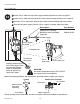
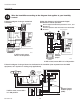
Wire the humidifier according to the diagram that applies to your humidity
control.
Follow this diagram if using a mechanical
humidistat.
HVAC
RECOMMENDED
AIR FLOW
SWITCH (AFS)
MECHANICAL
HUMIDISTAT
HVAC
POWER
MASTER
THERMOSTAT
HUM
HUM
GYWRRc
GYWR C
HUMIDIFIER - INTERNAL
24V
24V
HUM
HUM
C
GT
R
RT
GF
EXT
M29029
Factory
installed
jumper
If AFS is used, ensure
DIP 5 is in ON position.
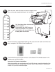
Follow this diagram to wire Automatic Digital
Humidistat for manual operation.
Set the digital humidistat ISU parameter 10 to 1, and
ISU 25 to 2.
A
For auto-operation: also wire W and G to thermostat
W and G.
B
HVAC
DIGITAL HUMIDISTAT
THERMOSTAT
HUM
HUM
R
C
GYWRRc
GYWRC
24V
24V
HUM
HUM
C
GT
R
RT
GF
EXT
RECOMMENDED
AIR FLOW
SWITCH (AFS)
M29030
HVAC
POWER
MASTER
HUMIDIFIER - INTERNAL
Factory
installed
jumper
If AFS is used, ensure DIP 5 is in ON position.
A
B
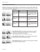
Follow this diagram if using a blower fan dedicated to the humidifier (a fan separate from the HVAC
equipment, as in hydronic or cooling-only applications).
24V
24V
HUM
HUM
C
GT
R
RT
GF
EXT
HUMIDISTAT
HUM
HUM
HAC
HAC
MECHANICAL
HUMIDISTAT
HUM
HUM
HAC
HAC
RECOMMENDED
AIR FLOW SWITCH
(AFS)
HUMIDIFIER - INTERNAL
HVAC
120 VAC
RELAY
RED
BLACK
L1
L2
120
VAC
AT120
RC
M29031
HVAC POWER MASTER
Remove Factory
installed jumper
(R/RT)
If AFS is used, ensure DIP 5
is in ON position.