
Technical data
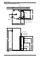

INSTALLATION
6
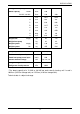
MAINS WATER SUPPLY
Where the mains water supply pressure exceeds that shown in the table below,
an approved pressure limiting valve is required. Refer to the Owner‟s Guide
and Installation Instructions supplied with the storage tank for the position of
the pressure limiting valve.
Model
325, 410
Relief valve setting
1000 kPa
Expansion control valve setting *
850 kPa
Max. mains supply pressure
With expansion control valve
680 kPa
Without expansion control valve
800 kPa
Min. mains supply pressure
200 kPa
* Expansion control valve not supplied with the water heater.
A minimum water supply pressure of 200 kPa is required to enable the heat
pump circulator and heat pump system to operate effectively.
TANK WATER SUPPLY
If the water heater is supplied with water from a tank supply and a minimum
water supply pressure of 200 kPa at the water heater cannot be achieved, then
a pressure pump system must be installed to allow the heat pump circulator to
operate and avoid air locks in the circuit. Care must be taken to avoid air locks.
The cold water line from the supply tank should be adequately sized and fitted
with a full flow gate valve or ball valve.
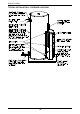
CONDENSATE DRAIN
A drain line should be fitted to the heat pump module‟s condensate drain to
carry the discharge clear of the water heater. The drain line can be extended
using 12 mm rigid poly hose or conduit. The pipe work from the condensate
drain should be as short as possible and fall all the way from the water heater
with no restrictions. It should have no more than three right angle bends in it.
The outlet of the drain line must be in such a position that flow out of the pipe
can be easily seen - but arranged so water discharge will not cause damage or
nuisance.
The condensate drain line must not be connected to the relief valves
drain lines but may discharge at the same point.