
Technical data


HEAT PUMP AND TANK ASSEMBLY
13
ASSEMBLY PROCEDURE
Warning: The heat pump must be assembled, plumbed and filled with
water prior to power being connected and switched on.
The following procedure should be followed to properly place the heat pump
module in position and connect to the storage tank:
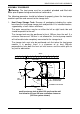
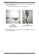
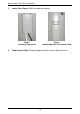
1. Heat Pump Storage Tank: Remove all packaging including the carton
base from the heat pump storage tank and position in its intended location,
supported by a level slab or solid base.
The water connections may be on either the left or right hand side and
should be parallel to the wall.
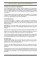
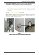
The storage tank must be positioned at least 100 mm from the wall. If a
minimum clearance of 100 mm is not allowed for, the heat pump module
will not be able to be completely connected to the storage tank.
The storage tank must also be positioned such that when the heat pump
module is in position, there is a clearance of at least 300 mm
perpendicular from both the front air inlet louvres and the outlet grille to
any wall or obstruction.
1631
1317
1018
32°
574
HOT
OUTLET
COLD
INLET
114
546
871
863
619 245
100
WALL
AIR
INLET
AIR INLET
638
AIR
OUTLET
300 MIN
VENTILATION
CLEARANCE
CONDENSATE DRAIN
TPR
VALVE
AIR INLET
AIR
OUTLET
300 MIN
162
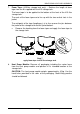
HEAT PUMP DIMENSIONS - 325L
SK6499 A4
REV BD 5/08
300 MIN
ELECTRICAL
CONNECTION
VENTILATION
CLEARANCE
Step 1
position storage tank at least 100 mm from the wall
and allow for at least 300 mm ventilation clearance
(325 litre system shown)