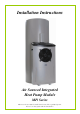
Installation Instructions Air Sourced Integrated Heat Pump Module MPi Series This water heater must be installed and serviced by a qualified person. Please leave this guide with the householder.
PATENTS This water heater may be protected by one or more patents or registered designs in the name of Rheem Australia Pty Ltd. ® TRADE MARKS Registered trademark of Rheem Australia Pty Ltd. ™ Trademark of Rheem Australia Pty Ltd. Note: Every care has been taken to ensure accuracy in preparation of this publication. No liability can be accepted for any consequences, which may arise as a result of its application.
CONTENTS HOUSEHOLDER – This installation instruction booklet is intended for the installer but you may find it of interest. Installation .............................................................................................. 4 Heat Pump And Tank Assembly ......................................................... 11 Connections – Electrical ..................................................................... 26 Commissioning ...........................................................................
INSTALLATION INSTALLATION STANDARDS The water heater must be installed: by a qualified person, and in accordance with the installation instructions, and in compliance with Standards AS/NZS 3500.4, AS/NZS 3000 and all local codes and regulatory authority requirements. In New Zealand, the installation must also conform with Clause G12 of the New Zealand Building Code. WATER HEATER APPLICATION This water heater is designed for use in a single family domestic dwelling for the purpose of heating potable water.
INSTALLATION Care must be taken during transportation and handling. Do not lay the heat pump module down and do not tilt the heat pump module or the heat pump and storage tank assembly more than 30° from the vertical. This will displace the compressor lubricating oil.
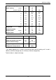
INSTALLATION MAINS WATER SUPPLY Where the mains water supply pressure exceeds that shown in the table below, an approved pressure limiting valve is required. Refer to the Owner‟s Guide and Installation Instructions supplied with the storage tank for the position of the pressure limiting valve. Model 325, 410 Relief valve setting 1000 kPa Expansion control valve setting * 850 kPa Max. mains supply pressure With expansion control valve 680 kPa Without expansion control valve 800 kPa Min.
INSTALLATION WARNING This water heater is only intended to be operated by persons who have the experience or the knowledge and the capabilities to do so. This water heater is not intended to be operated by persons with reduced physical, sensory or mental capabilities i.e. the infirm, or by children. Children should be supervised to ensure they do not interfere with the water heater.
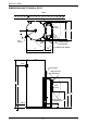
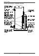
INSTALLATION DIMENSIONS AND TECHNICAL DATA WALL 100 AIR INLET AIR OUTLET 574 C 30 H 0M IN IN 0M 30 AIR TPR VALVE VENTILATION CLEARANCE INLET 245 K CONDENSATE DRAIN B HOT OUTLET AIR INLET 30 0 M IN VENTILATION CLEARANCE A D AIR OUTLET 1018 871 ELECTRICAL 546 CONNECTION COLD INLET F E HEAT PUMP DIMENSIONS 8 325 & 410 INTERGRATED
INSTALLATION Storage tank capacity litres 325 410 1.8 kW litres 100 - 2.4 kW*, 3.
INSTALLATION TYPICAL INSTALLATION – OUTDOOR LOCATION TYPICAL INSTALLATION HEAT PUMP WATER HEATER - 325L 10
HEAT PUMP AND TANK ASSEMBLY STORAGE TANK AND HEAT PUMP MODULE The heat pump water heater is made of two main components, the storage tank and the heat pump module. For transport and handling (weight) purposes both items are shipped separately and designed to be assembled at the installation site. The water heater must not be operated until both components are assembled. The heat pump storage tank and module must be installed on a level slab or solid base of a minimum 900 mm wide x 650 mm deep.
HEAT PUMP AND TANK ASSEMBLY storage tank heat pump module + heat pump water heater = KIT There is a kit supplied with the heat pump module (PN 080199) and a kit supplied with the 410 model heat pump storage tank (PN 290122). The components supplied in the kit and required for the installation are: 080199 Kit Installation Heat Pump Module Integrated Qty 126558 Installation instructions heat pump module integrated 1 052158 Saddle clamp 20 mm Clipsal 261/20 1 080021 Screw phillips pan head No.
HEAT PUMP AND TANK ASSEMBLY ASSEMBLY PROCEDURE Warning: The heat pump must be assembled, plumbed and filled with water prior to power being connected and switched on. The following procedure should be followed to properly place the heat pump module in position and connect to the storage tank: Heat Pump Storage Tank: Remove all packaging including the carton base from the heat pump storage tank and position in its intended location, supported by a level slab or solid base.
HEAT PUMP AND TANK ASSEMBLY 2. Lower Front Cover: Remove the two screws securing the lower front cover to the storage tank. Remove the lower front cover from the storage tank. Step 2 remove screws from lower front cover 3. Step 3 withdraw the power cable Power Cable: Withdraw the power cable, housed behind the lower front cover, from the opening.
HEAT PUMP AND TANK ASSEMBLY 4. Mains Power Connection: Connect the mains power supply wiring to the terminal block and earth connection inside of the lower front cover. Secure the conduit to the side of the storage tank with a saddle clamp. The saddle clamp must be positioned over the pilot holes provided, otherwise the conduit will interfere with the heat pump module installation. Refer to “Connections – Electrical” on page 26.
HEAT PUMP AND TANK ASSEMBLY 5. Lower Front Cover: Refit the lower front cover. Step 5 refit lower front cover 6. Step 6 remove tape from tank sensor cable Tank Sensor Cable: Remove tape from tank sensor cable and unfurl.
HEAT PUMP AND TANK ASSEMBLY 7. Foam Tape: (410 litre storage tank only) – Retrieve the length of foam tape from the kit supplied with the 410 storage tank. The foam tape is to be applied to the bottom at the front of the 410 litre storage tank. The ends of the foam tape are to line up with the two vertical slots in the jacket. The mid point of the tape (lengthways) is to line up over the join between the jacket of the storage tank and the jacket bottom.
HEAT PUMP AND TANK ASSEMBLY 9. Cover Strip: (410 litre storage tank only) – Retrieve the length of rubber cover strip from the kit supplied with the 410 storage tank. Line up one end of the cover strip with one end of the heat pump housing black top, fitting the strip over the lip of the housing, ensuring the jacket is hard up against the lip of the heat pump housing. The cover strip will hold the jacket in position. Apply the cover strip along the full length of the lip of the heat pump housing.
HEAT PUMP AND TANK ASSEMBLY 10. Heat Pump Module Cover: Remove the two screws securing the front cover to the heat pump module. Remove the front cover from the heat pump module. Step 10 and 12 remove front cover from heat pump module and feed through cables 11. Position Heat Pump Module: Position the edge of the heat pump module which is closest to the wall against the storage tank so the screw holes in the module are adjacent to the nutserts in the storage tank. 12.
HEAT PUMP AND TANK ASSEMBLY 14. Cold Hose Connection: Attach the flexible braided hose, marked with a blue collar from the bottom of the heat exchanger, to the fitting in the bottom connection on the storage tank and marked “INLET” in blue. Tighten the swivel nut on the hose using a 24 mm spanner. Tape or sealant is not required. Position the hose such that when the heat pump module is moved and secured to the tank, it does not kink.
HEAT PUMP AND TANK ASSEMBLY 15. Hot Hose Connection: Attach the flexible braided hose, marked with a red collar, from the top of the circulator to the fitting in the top connection on the storage tank and marked “OUTLET” in red. Tighten the swivel nut on the hose using a 24 mm spanner. Tape or sealant is not required. Position the hose such that when the heat pump module is moved and secured to the tank, it does not kink. Step 15 attach flexible hose with red collar to outlet 16.
HEAT PUMP AND TANK ASSEMBLY 17. Cable Tab: Remove the tab on the side of the electrical entry to the heat pump module to accommodate the electrical conduit. Pliers or tin snips may be required to remove the tab. Step 17 remove the tab on the side of the electrical entry to the heat pump module 18. Studs: Retrieve the three (3) studs from the kit and screw into the three (3) threaded inserts on the side of the tank closest to the wall.
HEAT PUMP AND TANK ASSEMBLY 19. Position Heat Pump Module: Position the heat pump module against the tank. Engage the tab at the bottom of the heat pump module, on the wall side of the module, into the slot in the tank. Align the holes in the side of the heat pump module over the three studs. 20. Flange Nuts: Screw the three flange nuts onto the studs to connect the wall side of the heat pump module to the storage tank.
HEAT PUMP AND TANK ASSEMBLY 23. Tank Sensor Cable Connection: Insert the tank sensor cable plug to the connector on the underside of the control box. The plug is polarised and can only be inserted one way. Ensure the plug fully engages the locking feature on the connector. 24. Power Cable Connection: Insert the four pin power cable plug to the connector on the underside of the control box. The plug is polarised and can only be inserted one way.
HEAT PUMP AND TANK ASSEMBLY 25. Positioning of Water Heater: Complete final positioning of the water heater. Ensure the heat pump module is firmly seated on the level slab or solid base. 26. Water Connections: Connect the cold water supply and the hot water pipe work to the water heater. Connect the temperature pressure relief valve and its drain line. Refer to “Connections – Plumbing” in the Owner‟s Guide and Installation Instructions supplied with the storage tank. 27.
CONNECTIONS – ELECTRICAL The power supply to the water heater must not be switched on until the water heater is filled with water and a satisfactory megger reading is obtained. MEGGER READING When a megger test is conducted on this water heater, then the following should be noted. Warning: This water heater contains electronic equipment and 500 V insulation tests must only be conducted between active and earth and between neutral and earth. An active to neutral test WILL damage the electronics.
CONNECTIONS – ELECTRICAL WIRING DIAGRAM THERMOSTAT BLUE BROWN LIGHT RED BLACK BLUE LIGHT RED C COMPRESSOR CAPACITOR RED CONTROL BOARD BLUE R S BLACK COMP-N COMP-A GREEN/YELLOW COMPRESSOR PLUG BLACK RED BROWN BLUE BLUE BLACK GREEN/YELLOW GREEN/YELLOW NC NO RED COM T2 - Compressor Thermistor T1 - Evaporator Thermistor T0 - Tank Thermistor Remote LED Display BLUE PUMP EARTH FAN CAPACITOR FAN PLUG CABLING INSIDE TANK JACKET NEUTRAL GREEN/YELLOW FAN FAN-A FAN-N PUMP-N PUM
COMMISSIONING TO FILL AND TURN ON THE WATER HEATER The power supply to the water heater must not be switched on until the water heater is filled with water and a satisfactory megger reading is obtained. Open all of the hot water taps in the house (don‟t forget the shower). Open the cold water isolation valve fully to the water heater. Air will be forced out of the taps. Close each tap as water flows freely from it.
COMMISSIONING Note: The heat pump may not turn on after either having just completed a heating cycle and more hot water is drawn from the water heater or power is shut down to the compressor, either during or at the end of a heating cycle. The heat pump will wait until the compressor has cooled down and the conditions for start up are favourable in order to protect the compressor from damage.
COMMISSIONING The modes are: Flashes solid green (remains on) Operational Modes Standby mode – water is hot 1 x green Call for heating received – system checks performed Note: unit may wait and continue flashing until compressor has cooled from its last operation 2 x green Circulator commences circulation 3 x green Heat pump operation – compressor and fan running long green Heating unit on – ambient air temperature below 3°C to 5°C or above 45°C to 55°C no green (remains off) Flashes No power at
COMMISSIONING Time controlled power supply (power must be available at the water heater) If the water heater is connected to a time controlled power supply, then during periods of no power supply at the water heater the LEDs will be off. This is not a fault condition, but a result of no power being available to energise the LEDs. The green LED will recommence glowing or flashing when power is available again at the water heater.
WATER SUPPLIES This water heater must be installed in accordance with this advice to be covered by the manufacturer’s warranty. This water heater is manufactured to suit the water conditions of most public reticulated water supplies. However, there are some known water chemistries which can have detrimental effects on the water heater and its operation and / or life expectancy. If you are unsure of your water chemistry, you may be able to obtain information from your local water supply authority.
WATER SUPPLIES CHLORIDE AND PH Where the chloride level exceeds 250 mg/L the manufacturer‟s warranty does not apply to the water heater. In a high chloride water supply, the water can corrode stainless steel parts and cause them to fail. Where the pH is less than 6.0 the manufacturer‟s warranty does not apply to the water heater. pH is a measure of whether the water is alkaline or acid. In an acidic water supply, the water can attack stainless steel parts and cause them to fail.
This page is intentionally blank.
WARRANTY NOTE The heat pump water heater is covered by the manufacturer‟s warranty. For full manufacturer‟s warranty details, refer to the Owner‟s Guide and Installation Instructions supplied with the storage tank. The part extracts from the “Terms Of The Warranty And The Exclusions To It” of the water heater warranty should be noted before commencing the installation. TERMS OF THE WARRANTY AND EXCLUSIONS TO IT 2.
Revision Date: 2012 May 126558H 36