
Specification Sheet
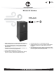
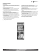


Air
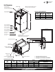
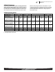
Airflow Performance Data
RHML Series
8
Model
No.
RHML
Nominal
Cooling
Capacity
Tons
Motor
Speed
From
Factory
Manufacturer
Recommended
Air-Flow Range
(Min/Max) CFM
Blower Size/
Motor
HP
# of Speeds
Y1, Y2
Speed
Motor
Speed
X-13 Wet Coil No Filter CFM Air Delivery/RPM/Watts-230 Volts
External Static Pressure—Inches W.C. [kPa]
0.1 [.02] 0.2 [.05] 0.3 [.07] 0.4 [.10]
0.5 [.12] 0.6 [.15]
0.7 [.17] 0.8 [.20]
0.9 [.22] 1.0 [.25]
-2421
No Heater
2.0
Y1 Tap 4
Y2 Tap 5
Y1=310/817 CFM
[146/385] L/s
Y2=445/951 CFM
[210/448] L/s
10X8
3/4 hp 5 speed
Y1
Low Static
Tap 2
CFM
740
569 310 —
— —
— — —
—
RPM
542 561
584 —
— —
— —
—
—
Watts
94
72
49 — — —
—
— — —
Y2
Low Static
Tap 3
CFM
851
704 653
590 541 489
445 —
— —
RPM
578
599 647 711 770
814
868 — — —
Watts
88 93 98 103 108 113 118 — — —
Y1
High Static
Tap 4
CFM
817
699 574
515 — —
—
— — —
RPM
573
588 630 702
— —
— — —
—
Watts
97 88 78 69 —
—
— — — —
Y2
High Static
Tap 5
CFM
951
911
872 824 787 742
691
— — —
RPM
622 672 725 772 821 880 922 — — —
Watts
134 146 157 168 179 191 202 — — —
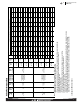
-2421
With 13 kW
Heater
2.0
Y1 Tap 4
Y2 Tap 5
Y1=290/797 CFM
[136/376] L/s
Y2=425/931 CFM
[200/439] L/s
10X8
3/4 hp 5 speed
Y1
Low Static
Tap 2
CFM
720
549 290
—
— — — —
—
—
RPM
557 576
599
—
— —
—
—
— —
Watts
99 77 54
— —
— —
— — —
Y2
Low Static
Tap 3
CFM
831
684 633 570
521 469
425 — —
—
RPM
593 614 662 726 785 829 883 — —
—
Watts
93
98
103 108 113 118
123
— — —
Y1
High Static
Tap 4
CFM
797
679 554
495 — —
— —
— —
RPM
588
603 645 717 —
—
— — — —
Watts
102
93 83
74 — —
—
— — —
Y2
High Static
Tap 5
CFM
931
891 852
804 767 722
671 —
— —
RPM
637
687 740 787
836 895
937 — —
—
Watts
139 151 162 173 184 196 207 — — —
Airflow Performance Data
Notes: • All 208/240V PSC motors have voltage taps for 208 and 240 volts.
• All 208/240V PSC motors are shipped on high speed and 240 volts.
• If the application external static is less than 0.5" WC, adjust the motor speed to the low static speed as described below:
• Unplug the black motor wire off the relay on the control board and plug in the red motor wire.
• Replace the cap on the black motor wire.
• Voltage change (208/240V motors):
• Move the orange lead to transformer 208V tap from 240V tap. Replace the wire cap on 240V tap.
• Unplug the purple motor wire off the transformer and plug in the yellow motor wire.
• Replace the cap on the purple motor wire.
• The above airflow table lists the airflow information for air handlers without heater and air handler with maximum heater allowed for each model.
• The following formula can be used to calculate the approximate airflow, if a smaller (N kW) than the maximum heater kit is installed.
Approximate Airflow = Airflow without heater - (Airflow without heater - Airflow with maximum heater) x (N kW/maximum heater kW)
[ ] Designates Metric Conversions