
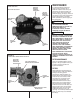
Use & Care Manual


OFF - Turns heating and cooling modes
off. (The blower may still circulate air in
the FAN-ON position.)
FAN-ON - Turns the blower on for
continuous operation.
FAN-AUTO - The blower cycles on and
off with cooling or heating operation.
This furnace has a negative pressure
switch that is a safety during a call for
heat. The induced draft blower must
pull a negative pressure on the heat
exchanger to close the negative
pressure switch. The induced draft
blower must maintain at least the
negative pressure switch set point for
the furnace to operate. If the induced
draft blower fails to close or maintain
the closing of the negative pressure
switch, a “no heat call” would result.
LIGHTING INSTRUCTIONS
DIRECT SPARK IGNITION
This appliance is equipped with a direct
spark ignition device. This device lights
the main burners each time the room
thermostat (closes) calls for heat. See
lighting instructions on the furnace.
TO START FURNACE
NOTE: DURING INITIAL START UP
OF THE FURNACE, IT IS NOT
UNUSUAL FOR ODOR OR SMOKE
TO COME OUT OF ANY ROOM
REGISTERS. IT IS RECOMMENDED
TO ENSURE PROPER VENTILATION
BY OPENING WINDOWS AND
DOORS BEFORE INITIAL FIRING.
1. BE SURE THAT THE MANUAL
GAS STOP HAS BEEN IN THE
“OFF” POSITION FOR AT LEAST
FIVE MINUTES. DO NOT ATTEMPT
TO MANUALLY LIGHT THE MAIN
BURNERS. FAILURE TO FOLLOW
THIS WARNING CAN CAUSE A
FIRE OR AN EXPLOSION
RESULTING IN PROPERTY
DAMAGE, PERSONAL INJURY OR
DEATH.
2
. Set the room thermostat to the
lowest temperature setting.
3. Remove furnace panel.
4. Turn the gas control knob to the
“On” position, or set the gas control
switch to the “On” position.
5. Securely replace furnace panel.
6. Turn on the manual gas stop and the
electrical power.
7
. Set the room thermostat to “Heat”
and adjust to desired room
temperature.
TO SHUT DOWN FURNACE
1. Set the room thermostat to its lowest
temperature setting. Turn the
thermostat to “Off.”
2. Shut off the gas to main burners by
turning the gas control switch to the
“Off” position, or turn the manual gas
stop to the closed position.
SHOULD OVERHEATING OCCUR
OR THE GAS SUPPLY FAIL TO
SHUT OFF, SHUT OFF THE MANUAL
GAS STOP TO THE APPLIANCE
BEFORE SHUTTING OFF THE
ELECTRICAL SUPPLY. FAILURE TO
DO SO CAN CAUSE AN EXPLOSION
OR FIRE RESULTING IN PROPERTY
DAMAGE, PERSONAL INJURY OR
DEATH.
NOTE: Sequence of operation can be
located in the Installation instructions,
in the start-up procedure section. This
covers operation of the furnace with
single-stage or two-stage thermostats.
4
!
WARNING
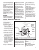
FIGURE 4
BURNER COMPARTMENT - SHOWING LOCATION OF TYPICAL GAS CONTROLS
MANUAL GAS VALVE
UNION
DRIP LEG
BURNERS
MANIFOLD
GAS VALVE
I524
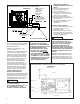
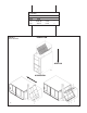
!
WARNING
F
IGURE 3
B
URNER COMPARTMENT – SHOWING LOCATION OF GAS CONTROLS
CONDENSATE TRAP
DRAIN LINE
a103101
T
O FLOOR DRAIN OR CONDENSATE PUMP
NOTE:
D
RAIN VENT NEEDS
TO BE ABOVE
COLLECTOR BOX
D
RAIN SPOUT.
NEUTRALIZER CARTRIDGE
(OPTIONAL)
OVERFLOW LINE
(REQUIRED ONLY WHEN
O
PTIONAL NEUTRALIZER
CARTRIDGE IS USED.)
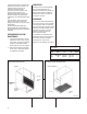
MINIMUM HEIGHT
OPEN TOP
DOWNFLOW
HORIZONTAL